9

I have a set of LED driving lights on my motorcycle that must be wired through a ground-leg pulse width modulation dimmer. The problem is the mounting bracket for the lights is grounded, so the lamp shorts to ground through the motorcycle chassis and the PWM dimmer cant dim the lamps. I had solved this issue by isolating the lamps from the motorcycle's chassis at the mounting point, but this has proved unreliable in the rain, and the brackets I had to use weren't up to the task and eventually broke.

I now need to look at internally isolating the lamp housing from the ground leg of the circuit. I had hoped that when I opened up the lamp there would be a separate grounding lead screwed to the light housing that i could simply disconnect, but it appears that the housing is grounded simply by the contact between the PCB and the housing, plus the PCB mounting screws.

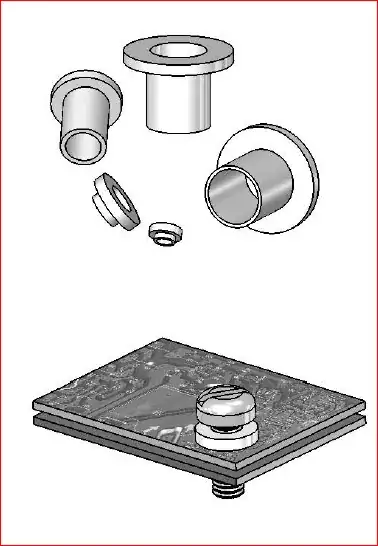
My first thought was to just put some small rubber o-rings between the PCB and the housing, and switch from steel to nylon screws for mounting the PCB, but then I remembered that the LEDs need a thermally conductive path to the housing for cooling.

So the question: how to provide a thermally-conductive, electrically-insulated mount for this PCB?

I've seen mention of mica washers, some mention of electrically-insulating heatsink compound, but nothing that seemed authoritative enough to scream "answer."

The PCB is probably 7cm square, and it is surface-mounted to the lamp housing/heat sink by 4 screws, one at each corner. The PCB's entire back appears to be aluminum--actually it looks more like the PCB is aluminum. More likely there is a very thin PCB laminated onto a piece of aluminum stock, pretty cool really, first I've seen like that.

mac
  • 192
  • 1
  • 1
  • 6
  • 2
    The typical solution you'll see is mica washer "strips" or "sheets"... small rectangular pieces of mica that match the shape of whatever they are isolating, usually transistors in the TO-220 package. You might be able to get away with mica sheets here since it looks like your interface area is similar in size to a TO-220 package. – Toby Lawrence Oct 26 '12 at 15:31
  • @TobyLawrence thanks, edited post to better specify the size of the PCB – mac Oct 26 '12 at 15:34
  • How about supplying -12V thru a +12 to -12 power inverter? A little more hardware but 15W inverter should be small & inexpensive. – Keith Warble Apr 15 '17 at 23:59

4 Answers4

12

Typical solutions I've used are either Kapton tape:

kapton tape

Or Sil-Pad:

Sil-Pad 400 is a composite of silicone rubber and fiberglass. The material is flame retardant and is specially formulated for use as a thermally conductive insulator. The primary use for Sil-Pad 400 is to electrically isolate power sources from heat sinks.

sil-pad

If you use a sil-pad the screw will still electrically connect the componet tab with the heat sink. A solution to this is to use a shoulder washer to isolate the screw and the tab:

shoulder-washer-diagram

AndrejaKo
  • 23,261
  • 25
  • 110
  • 186
embedded.kyle
  • 8,411
  • 2
  • 26
  • 44
  • The Sil-Pad seems more purpose-built for this type of application, but the formats in which it is sold are not great for my particular geometry. There also seems to be plenty of documented uses of Kapton tape for this application. I think that's how I'm going to proceed. Thanks! – mac Oct 26 '12 at 17:35
  • @mac You can buy Sil-Pad in sheets or rolls and then cut to fit. Of course then you'd have to dream up some application to use the rest of it on. But overall I think Kapton tape is probably cheaper and more readily available. – embedded.kyle Oct 26 '12 at 17:50
  • 2
    Unless you have a **LOT** of contact area, I wouldn't recommend kapton tape. Kapton is not exactly known for it's thermal conductance. In fact, this is the first time I have *ever* seen anyone recommend it as a thermal interface material. – Connor Wolf Oct 27 '12 at 00:55
  • 3
    @FakeName The question was "how to electrically isolate a PCB from a heat sink". Under "Applications" for [Kapton MT](http://www2.dupont.com/Kapton/en_US/products/MT/index.html) it suggests, "Insulation pads (heat sink)". And "Recommended Use" of [K275](http://www.stockwell.com/data_sheets/thermal/thermal_k275.pdf) is "Thermally conductive dielectric barrier". Yes, Kapton has less than 1/3 the thermal conductivity of Sil-Pad. But we're talking about 15W LED's. I've used Kapton up to a couple KW after which point it was necessary to switch to Sil-Pad to achieve desired performance. – embedded.kyle Oct 29 '12 at 12:58
  • 1
    Huh. I didn't know they made special thermally-conductive kapton variants. That's pretty cool! – Connor Wolf Oct 29 '12 at 21:26
  • Kapton tape worked great! – mac Nov 29 '12 at 16:51
2

The bracket of the lights is most likely grounded by design.

I can't think of a reason why a dimmer module and lights cannot both be grounded to the motorcycle, and not work except that the "IQ-170 Intelligent Lighting Controller" dimmer is actually not so intelligently designed. The geniuses who came up with this certainly did not have an IQ anywhere near 170. They didn't consider lights that are grounded to the chassis via their mounting hardware, and rely on that for heat dissipation too.

A properly designed dimmer will control the V+ side of the light, and not require its ground to be lifted, which, as you can see, creates difficulties.

You have a very good reason for returning this thing: it is technically flawed. I would contact the company for technical support. Perhaps the module can work on the other side of the lights.

Kaz
  • 19,838
  • 1
  • 39
  • 82
  • I agree that it would be a whole lot easier if the dimmer switched the +12V side, but alas, this is not the case. In fact, ground-leg switching seems more common on these types of devices than V+ switching, for whatever reason. Some other stuff on cars and motorcycles switch the ground leg too. Seems silly to me. – mac Oct 26 '12 at 16:02
  • In any case, the dimmer supplier should supply the necessary materials to deal with grounded heat sinks, without which their "kit" is incomplete. If it is advertized as a complete solution, then that is misleading if you have to buy additional parts to work around problems. Heat sink insulators and thermal grease do not fall out of the sky for free. – Kaz Oct 26 '12 at 19:01
  • @mac - Ground-leg switching is common because it's *really easy to implement*. However, doing high-side switching because it's slightly more involved is indicative of plain-old poor engineering. – Connor Wolf Oct 27 '12 at 00:57
1

What about Chomerics tape? It's non electrically conductive and very thermally conductive. http://www.chomerics.com/products/thermal/phase-change/index.html

Kind of looks like double stick tape when it's cool and turns into a sticky goo when it's hot. You might still need a clip or something to hold your heat sink down.

Some Hardware Guy
  • 15,815
  • 1
  • 31
  • 44
  • their website cautions against using this as an insulator, as once it goes liquid it can't prevent direct contact between the bonded elements. – mac Oct 26 '12 at 17:36
0

How to provide a thermally-conductive,
electrically-insulated mount for this PCB?""

How about electronics grade silicone, Just a thin coat.

rdivilbiss
  • 919
  • 1
  • 7
  • 12