I know it sounds dum and that I sound dum but theres such a large amount of MOSFETs out there, there are N-channel and P channel devices that have extremely similar functionalities, capabilities, rating's etc. why choose a PMOS or NMOS over the other when all the ratings are practically the same?
Asked
Active
Viewed 1,906 times
0
-
The ratings aren't the same... – DKNguyen Sep 01 '19 at 17:26
-
availability, price, reliability of the manufacturing process (affecting warrantee failures), package inductance, resilence to transients – analogsystemsrf Sep 01 '19 at 17:27
-
there extremely similar though – Hamza Arshad Sep 01 '19 at 17:33
-
Do you mean when select a N or P channel MOSFET when the all ratings are same ? – Mordecai Sep 01 '19 at 17:35
-
@Mordecai Oh, is that what he is asking? – DKNguyen Sep 01 '19 at 17:37
-
@DKNguyen I thought this what he is asking because otherwise it doesn't makes any sense to me – Mordecai Sep 01 '19 at 17:51
4 Answers
3
If you have two "similar" NPN and PNP transistors, or NMOS and PMOS FETs this is how you select which one to use.
- Due to semiconductor physics, the NPN and NMOS are always more efficient and smaller (aka faster and cheaper) than their PNP and PMOS counterparts. As a result, the NPN and NMOS also have much higher availability than the PNP or PMOS parts.
If the two look like they have similar ratings, you're probably not looking at all the specifications. The PNP/PMOS part must have a larger die to match some parameter of the NPN/NMOS part which means that is is sacrificing some other parameter. For example, for a PMOS to conduct as efficiently as an NMOS the PMOS die must be about twice as large which means the PMOS will have double the capacitance and therefore be half as fast. Or it can have the same die size band be the same speed but half as efficient.
- But an even bigger reason is how the part is controlled.
For NPN/PNP whatever is applied to the the base AND emitter terminals controls the BJT. Not JUST the base,
For a NMOS/PMOS, whatever is applied to the gate AND source terminals controls the MOSFET. Not JUST the gate.
Why is this important? It's important because the signal you are applying to drive the gate/base of the transistor is often referenced to a fixed voltage (i.e. usually ground, but sometimes a power rail). It is preferable to have the second terminal involved in controlling the transistor (the source or emitter) be connected to this fixed reference voltage, so that your applied control signal actually reflects what controls the transistor. (i.e. if you output 10V to control the transistor, 10V actually appears across the two terminals that control the transistor).
If you break this rule, then that means as the transistor conducts more or less, the voltage at the source/emitter terminal moves around based on the potentials of other components in the circuit as more or less current flows through them. If the reference your control signal uses no longer has the same reference as what the transistor is actually accepting as its control signal, then the control signal between your circuit's control output terminals is no longer what is actually arriving at the transistor's two control input terminals.
The directionality of NMOS and NPN devices make them the simplest to use when the control signal is referenced to ground (since the emitter/source can connect to ground so that the base/gate can be driven relative to ground).
The directionality of PMOS and PNP devices make them simpler to use when the control signal is referenced to a positive rail (since the emitter/source can connect to that rail and the gate/base can be driven relative to the positive rail).
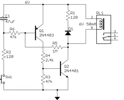
simulate this circuit – Schematic created using CircuitLab
However, sometimes an NMOS or NPN is so much more efficient (or available) compared to PNP and NPN you actually do break this rule (mostly in inverters, half-bridges, and H-bridges). But if you do this then you have to go to the effort of building a circuit that converts your your circuit's control signal (which is referenced to a fixed voltage, probably ground) into a signal whose reference "floats" with the reference terminal for the control signal on the transistor (source/emitter).
This floating signal isn't relative to ground and is output on two terminals. It is connected between the transistor's two control input terminals and its voltage floats to whatever the transistor's source/emitter pin is at so that the signal you are outputting actually appears across the transistor's two control input terminals, independent of the actual voltage that the transistor's terminals are sitting at.
NOTE: These circuits are for illustrative purposes. They don't work as shown and have numerous issues in real life.
DKNguyen
- 54,733
- 4
- 67
- 153
-
Thanks for making it more technical than my answer :) I was going to make my answer like this but I realized he can't understand it because if he can understand it he wouldn't ask a question like this – Mordecai Sep 01 '19 at 17:55
2
First and foremost, A PMOS is a "backwards" NMOS (and visa-versa). In an NMOS, in typical operation current flows from drain to source when the gate voltage is higher than the source voltage. In a PMOS, in typical operation current flows from source to drain when the gate voltage is lower the source voltage.
Second, and still quite important, you just can't get the same channel conductivity from a PMOS device as an NMOS device. This means that, for the same gate capacitance and technology generation, an NMOS device of a given RDS_on will have a lower gate capacitance and will thus be easier to drive.
This, in turn, is why there is a prevalence of NMOS transistors and specialized high-side gate drivers in high-power FET circuitry: it's cheaper and easier to use a complicated gate driver that lets you use an NFET than it is to try to source a PFET and drive its gate.
TimWescott
- 44,867
- 1
- 41
- 104
0
I'm assuming you're asking why chose a N channel MOSFET over P channel MOSFET :
1)Load's location 2)MOSFET's gate signal
1: if you want to add load between supply to MOSFET , you need to use N channel MOSFET
1:If you want to add load between MOSFET to ground , you need to use P channel MOSFET
2:If you signal is +V to 0V , you need to use N channel MOSFET because they conduct when signal is +V and stop at 0V
2:If your signal is 0V to -V , you need to use P channel MOSFET because they conduct when signal is -V and stop at 0V
Also main reason for component selection is price (if both components suitable for application)
Mordecai
- 409
- 2
- 7
- 15
0
there are N-channel and P channel devices that have extremely similar functionalities
This simply isn't true.
An n-channel MOSFET passes current through its channel when \$V_{gs}>V_{th}\$. A p-channel MOSFET passes current through its channel when \$V_{gs}<V_{th}\$.
This functionality is fundamentally different between n and p channel devices. You'll never find a p-channel device that behaves like an n-channel one in this respect, or vice versa.
The difference in functionality between the devices leads to most of the difference in applications between them. The advantage in performance for n-channel devices (when built with the same die area) drives most of the rest (and leads us to choose n-channel in most cases when we have the option to arrange our circuit to use either type).
The Photon
- 126,425
- 3
- 159
- 304