0

I'm using an ATMEGA3208 and I have configured the UART peripheral to open drain mode. I'm using an external pullup 1KΩ. I'm experiencing switching voltage spikes that goes negative. They are about 0.4V 500ns.

The spikes are only on receiver's side. The baud rate is 9600bps. The logic '1' is 3.3V.

I tried to increase the resistors to: R1 = R2 = 3KΩ. And R3 = R4 = R5 = R6 = 130Ω and the undershoot goes away. Of course that affects the logic '0' but it's still well below the threshold (0.3 x VCC).

They are exactly like this. However this answer doesn't help me as the mosfet is internal in the mcu. What can I do in this case?

EDIT: The undershoot is present even with 0.5m cables (multi copper standard wire 0.75mm)

Why does impedance matching matter in this case? Doesn't it matter only when the cables are much longer than signal's wavelength?

schematic

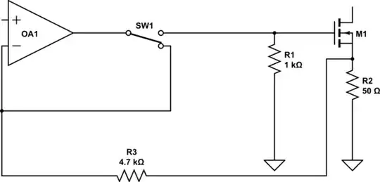
simulate this circuit – Schematic created using CircuitLab

MrBit
  • 1,973
  • 4
  • 27
  • 54
  • 1
    Other then baud-rate, you have also the rise and fall times of you signals. If those are fast, and you use long probe leads it can cause a measurement error, and not necessarily a real error. What is you measurement setup? What kind of probes do you use? – ZelmaB Aug 29 '19 at 13:30
  • @ZelmaB my measurement probe is fluke stl120 – MrBit Aug 29 '19 at 13:35
  • 1
    Overshoot is not uncommon, why do you consider it a problem? If you can identify the specific concern, to the extent that it is real, that can help chose the mitigation to address that concern. If that "20m" is a wire length, you first need to learn about transmission lines... – Chris Stratton Aug 29 '19 at 13:39
  • @ChrisStratton I'm a little worried about permanent damage in the mcu. Its absolute maximum rating is -0.5V – MrBit Aug 29 '19 at 13:40
  • You fix that with better ESD clamps, this is hardly the only cause of over voltage. Most likely however you have mismatched the line impedance. The source resistor and line impedance should initially halve the voltage so only reflection at the far end restores full voltage. – Chris Stratton Aug 29 '19 at 13:41
  • @ChrisStratton So I have to adjust the resistors in series to match line impedance, right? – MrBit Aug 29 '19 at 13:59
  • 2
    @MrBit, I can see several issue in your setup - the ATMEGA3208 data-sheet specifies rise\fall times of under 20nSec. Your probes BW is 12.5MHz -> meaning that you get 3dB attenuation at this BW or in other words the fastest change you can measure is 20nSec, which is not enough for your MCU. Also, as I mentioned before, these probes have a long ground lead. In order to get a better measurement, you need to use as short as possible wires and to place the probe as close as possible to your load. My bet is that by using better probing technique, you will see the over\undershoot disappear – ZelmaB Aug 29 '19 at 14:01
  • 3
    You could tune the resistance but it will never be perfect. Realistically if this is a 20 meter cable run you should use robust line driver receiver chips and probably skip the open drain (ie use RS485 or similar) – Chris Stratton Aug 29 '19 at 14:02
  • How is transmission line impedance defined? How can I calculate it? – MrBit Aug 29 '19 at 14:31
  • 1
    Why are you using open-drain mode in this application (point-to-point link) anyway? It really doesn't make sense, and any 20 m run of cable should have proper line drivers and receivers. The pins of an MCU were never intended for this. – Dave Tweed Aug 29 '19 at 15:22
  • @DaveTweed That is the right thing to do to address the issue at hand. – Steve Aug 29 '19 at 15:50
  • @DaveTweed This is a test from a multiplexed configuration I've done. There's another topic I wrote about it. Also if I increase the resistors to x3 times greater the undershoot goes away. – MrBit Aug 29 '19 at 16:11
  • 1
    Possible duplicate of [multiple Open Drain UART over long distance](https://electronics.stackexchange.com/questions/455081/multiple-open-drain-uart-over-long-distance) - you only got into this problem by ignoring the advice you were already given in your existing question on this project. Further, you can't use source termination in a multiplexed network anyway - your two node test is completely invalid as a representation of that. – Chris Stratton Aug 29 '19 at 16:22
  • @ChrisStratton It's not duplicate it's an irrelevant question about the same project I have. The two node configuration in the schematic above is not a represantion of anything but exactly what the picture shows. Also my previous question does not have any answer nor question regarding the undershoot I described. – MrBit Aug 29 '19 at 18:05
  • 1
    No, it's not at all irrelevant. The fundamental problems with what you are trying to do were explained there. Your problem is that you refused to believe people, went ahead and did it the way that was explained wouldn't really work, and now you have the exact sort of problem people were trying to help you avoid... – Chris Stratton Aug 29 '19 at 18:37
  • "if I increase the resistors to x3 times greater the undershoot goes away." - problem solved! – Bruce Abbott Aug 30 '19 at 00:10
  • @ChrisStratton Could you please explain why impedance matching matter in my case? I thought impedance matching matters when the cables are way longer than signal's wavelength – MrBit Sep 01 '19 at 07:42

0 Answers0