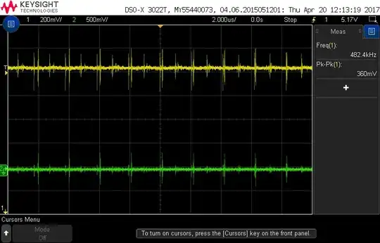
That largely depends on the exact chips involved and the physical layout and properties of your EEG circuit.
That said, if you are mainly worried about EMI due to proximity, adding a sheet of copper (or aluminum, although it doesn't work quite as well) foil tied to ground between the EEG part of the circuit and the transceiver can do a lot to reduce any interference.
This technique is used a lot in sensitive physics experiments. For example, when doing experiments with wave-particle duality for particles of non-negligible mass, basically all wires and equipment in the room will be wrapped in foil to prevent interference.
Side note: Unless I'm mistaken, most of the features of interest in an EEG are below a hundred Hz, so a low pass filter (such as the capacitor you mentioned) would probably work as well. To that end, when you are designing the boards, if you leave a spot for the capacitor, you can try it with and without and see if there is a difference. It's pretty common for initial prototypes to have extra components in the design that don't actually get installed during assembly - just in case you want to install it later.
Edit:
If ground contamination is a concern, you have a few options.
The simplest option from a component perspective is to use a split ground. Essentially, you have two separate grounds that are connected through a large number of narrow traces. This allows DC to flow, while attenuating high frequency noise at the boundary.
Another option (one used extensively in ECG/EKG circuits) is a form of active ground compensation. This entails using a feedback loop to force your ground plane to be zero. This is essentially noise cancelling for your ground plane.
Unfortunately in this case, you need an amplifier that can operate pretty significantly faster than your expected noise frequency.
A third option is to maintain two fully separate grounds, and allow the two subsystems to communicate through an isolated channel (opto-isolators, isolation transformers, etc.). The reason the data channels need to be isolated if your grounds aren't connected is that they won't have a common reference point, so at best it won't work and at worst you'll mangle your data or fry something.
Finally, you can put a filter in line with the ground line of your transmitter. This could be a very small value inductor in series with ground, and/or a collection of bypass capacitors.
