1

If I have a screw terminal block like in the picture below, is it normal practice to use one of the six connections for GND towards multiple external boards?

E.g. I wrap three wires into the rightmost connection and each of the three wires go to a separate board? (and likewise for VCC)?

Are there disadvantages to such method? It saves a lot of terminal blocks in my case.
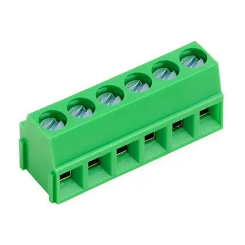
enter image description here

Michel Keijzers
  • 13,867
  • 18
  • 69
  • 139
  • 1
    Are you asking to put 3 wires into one connection in the terminal block? – Ron Beyer Aug 19 '19 at 20:13
  • @RonBeyer Yes I do. – Michel Keijzers Aug 19 '19 at 20:15
  • 1
    For reliability, I would not recommend more than one wire per terminal. If two or more wires are soldered together, and their combined wire gauge is within the terminal specifications, I might make an exception. – JYelton Aug 19 '19 at 20:15
  • @JYelton I think I can solder them together (they will be kind of fixed anyway), and there will be quite less power through it, one case some leds (20 mA max) and another case a MIDI In/Out/Thru board, which has a few inverters, an optocoupler and that's about it. – Michel Keijzers Aug 19 '19 at 20:18
  • 1
    Could always solder four wires together, then insert one end into this. – rdtsc Aug 19 '19 at 20:18
  • 2
    I prefer one wire per terminal. It is often difficult to get multiple wires into one terminal, and to be sure that all wires are held securely. However, I do sometimes try to get two or three wires in one terminal. – Peter Bennett Aug 19 '19 at 20:25
  • @PeterBennett Thanks for that info ... I think for the UARTs I will use separate terminal blocks, and for the LEDs I can add multiple wires, since I can very easily verify if they make good connections. – Michel Keijzers Aug 19 '19 at 20:28
  • @rdtsc Yes that sounds like a good idea. – Michel Keijzers Aug 19 '19 at 20:28
  • 2
    I would reccomend against putting soldered wires into clamping terminal blocks as the solder can cold-flow resulting in a bad join https://www.electronicspoint.com/forums/threads/do-dont-soldering-wire-tips-before-sticking-into-terminal-block.218528/ – Jasen Слава Україні Aug 19 '19 at 20:37
  • 1
    @Jasen good point ... if I want this, I better solder the wire 'before' inserting it in the terminal block (so the unsoldered combined wire will get the pressure). – Michel Keijzers Aug 19 '19 at 21:12

2 Answers2

1

Four is a lot of wires to put into a clamping terminal but if you twist them so that every wire is worked on by the clamp it can work reliably.

However untwisting and re-tristing whenever you need to re-work the joint is a hassle and requires contcentration to get it right, so a potential source of failure.

  • Yes, good point ... I think I can better try to make one GND connection to the LEDs and split it from there (if I make the LEDs close enough together). – Michel Keijzers Aug 19 '19 at 20:56
1

If you do, the boards will experience a common mode voltage. The common mode voltage will be generated by the current from each of the boards and the resistance of the connector. If the loads are switching current, this could be a problem for sensitive measurements or electronics.

You can find out if this is a problem by taking the max switching current and multiplying it by the resistance of the connector. Usually I use 0.1Ω as a max ball park number for connectors for thought experiments. V = I*R

If the max current was 0.1A, that would be 0.1A*0.1Ω=10mV -- probably not a problem

If the max current was 5A, that would be 5A*0.1Ω=50mV -- that might be a problem

Voltage Spike
  • 75,799
  • 36
  • 80
  • 208
  • I understand about half what you write (which says more about me than you, being a hobbyist), but seeing the last two sentences, I am certain it's not a problem for me. The only current that needs to be supplied is for a 6N137 optocoupler, an inverter and some resistors and capacitors. – Michel Keijzers Aug 19 '19 at 20:55
  • 1
    If it's low current and no switching then you are probably fine. – Voltage Spike Aug 19 '19 at 20:56
  • What do you mean with switching? The VCC and GND do not 'switch', unless I also use the UARTs this way (which have a speed of 31,250 bps). – Michel Keijzers Aug 19 '19 at 20:58
  • 1
    Is the UART going through the terminal? – Voltage Spike Aug 19 '19 at 20:59
  • Yes, but I will not combine multiple UARTs, just the VCC/GND toward to them (or at least, I can chose for that, depending on the risk). The UARTs RX/TX will each have their own terminal (thus 4 x RX/TX = 8). On the other hand, I wouldn't mind for the UARTs to have dedicated VCC/GND connections. – Michel Keijzers Aug 19 '19 at 21:01
  • 1
    You might see up to ~1mV of switching noise from the uarts on the ground. hard to say without analyzing the whole thing \ – Voltage Spike Aug 19 '19 at 21:03
  • 1
    1 mV seems nothing to me, having a range from 0 - 5V for RX/TX signals. – Michel Keijzers Aug 19 '19 at 21:03
  • 1
    If you have multiple UARTs, with separate cables going off in different directions for each one, I would definitetly have a separate GND terminal for each one, so I could disconnect the cable to one UART without affecting the other UARTs. – Peter Bennett Aug 19 '19 at 21:27