2

I'm a bit overwhelmed by the sheer amount of variations in optocouplers and since I've never used one before in any project I don't really know what criteria to look out for.

A colleague of mine suggested that I should replace the relays in my circuit with optocouplers as they are much cheaper and also smaller in size. I agree with him once I looked into it, but unlike relays, I'm very unfamiliar with optocouplers.

I have this schematics in which I use relays to enable/disable a parallel resistor.

schematic

simulate this circuit – Schematic created using CircuitLab

From my understanding, if I were to use optocouplers I could get rid of the TPIC6C596, which I only need due to the high current draw of the relay.

So for this output-schematic I figured I could use this LTV-847 which would replace 4 relays at once.

But there were many other options to choose from and I just feel like I'm making a wrong choice because the above was simply the cheapest 4 channel chip that I found.

It's a simple circuit without much timing constraints, so any optocoupler that uses less mA than a relay and handles 24V could work.

For relays it was a bit easier, because I needed the smallest, cheapest 5V relay that I can get, which narrowed down the search quickly.

But with optocouplers pretty much all of the options are cheaper than the relays, are smaller and also use less current...

Edit:

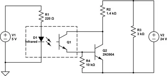
Would this circuit produce the same result as the relays?

schematic

simulate this circuit

Is my optocoupler choice fitting for the scenario, given that I have 24V on the input module and 5V on the control side. Basically just requiring a "switch" solution but in a smaller form factor.


Regarding my schematic:

Originally I used relays because I knew they don't produce a voltage drop on the output.

However, from what I've read, optocouplers do produce voltage drops because of the phototransistor used.

But since I'm unfamiliar with the component itself I didn't know how I could best reproduce the result of a relay with an optocoupler, meaning I can get the ~24mA needed on the output side.

The relay simply creates a parallel resistor, so the total resistance is around 1K ohm.

Would I need to lower the resistance of the output resistor R3 or are there optocouplers with identical results as relays?

HackXIt
  • 163
  • 8
  • 2
    Possible duplicate of [What are the differences between optoisolator output styles?](https://electronics.stackexchange.com/questions/187706/what-are-the-differences-between-optoisolator-output-styles) – CL. Aug 08 '19 at 20:37
  • Thanks for the link. I'll adjust the question, as it is not directly about the types of optocouplers.. – HackXIt Aug 08 '19 at 21:17
  • I don't see how you can replace 4 relays at once, it is a 4 pin optocoupler but it has 2 inputs and 2 outputs only. – Juan Aug 09 '19 at 00:56
  • "...the ~240mA needed on the output side" - your schematic suggests it only needs to switch 16mA. Where does the 240mA come from? What is the purpose of the two resistors? – Bruce Abbott Aug 09 '19 at 03:46
  • @Juan: The one I found was a 4 channel optocoupler, so it has 4 inputs/outputs. – HackXIt Aug 09 '19 at 10:59
  • @BruceAbbott: I adjusted the schematic. I know I've just put a voltage source there, but I can't always put in a full schematic, as it would blow up the question significantly. That's also why I left out the controls for the shift registers. The circuit on the output of the relay is a monitored input of another module. This module is in "off" state with the 3k resistor and in "on" state with a 1k resistor (parallel resistance of 3K & 1K5) – HackXIt Aug 09 '19 at 10:59
  • @BruceAbbott: Sorry, just noticed that this is incorrect. I meant 24mA. – HackXIt Aug 09 '19 at 11:37
  • You can get results that are *close* to a relay with an optocoupler using a direct connect and get virtually the same results if you use the optocoupler to operate a high side switch (which can have an on resistance measured in milliohms depending on device). – Peter Smith Aug 09 '19 at 13:48

1 Answers1

2

Optocouplers like the LTV-846 consist of an infrared LED and an NPN transistor. Output characteristics are similar to a normal bipolar transistor, except that Base current is created from light generated by the LED. This is not very efficient so despite the transistor's current gain the CTR (Current Transfer Ratio) is often less than 1.

In your circuit the LED current is about (5V-1.2V)/220Ω = 17mA, and the transistor has to switch 24V/1.5kΩ = 16mA. Therefore the CTR needs to be at least 1, preferably higher to ensure that the transistor is fully saturated for low voltage drop.

The LTV-846 is available in several 'ranks' depending on CTR. You should choose the B, C, or CD version, which have a minimum CTR of 2 or higher.

If your supplier doesn't have the high CTR version or the price is too high then you have a few other options. One is to use the optocoupler to turn on another transistor in Darlington configuration. This has a minimum voltage drop of ~0.8V, which will reduce the resistor current by about 0.7mA at 24V. If this is a concern then you could reduce the resistance from 1.5kΩ to 1.4kΩ.

schematic

simulate this circuit – Schematic created using CircuitLab

R4 ensures that the external transistor won't turn on due to leakage current from the optocoupler transistor.

Since Q2's current gain is >40 you could reduce LED current, perhaps enough to eliminate the TPIC6C596. Raspberry Pi GPIO outputs have a recommended maximum output current of 3mA, which should be enough to reliably operate the circuit even with a CTR of only 0.5. R1 would then be ~(3.3V-1.2V)/3mA = 680Ω (nearest 5% value).

Bruce Abbott
  • 55,540
  • 1
  • 47
  • 89
  • But R4 will also affect the current at the Input module, or not? – HackXIt Aug 10 '19 at 11:30
  • Actually I'll take your suggestion and clarify some things with my colleague about this input module and how it operates, which should make circuit design a bit more clear when I have concrete numbers about the input module. – HackXIt Aug 10 '19 at 11:34