You could do something like in the schematic below. Let R2 be your NTC.
It's probably best if you replace R5 with a potentiometer do be able to adjust your threshold.
As long as V+ of the OPAMP is lower than V-, its output is pulled low so the LED will not be lit. With the temperature increasing, the reistance of R2 will drop and V- will sooner or later be lower than V+, so the OPAMP will pull the output high and the LED goes on.
This just works well if you have one specific temperature threshold wo which you can calibrate the circuit. Keep in mind that NTCs have non-linear characteristics.
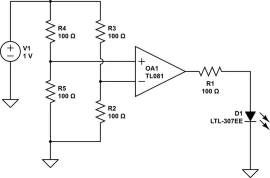
simulate this circuit – Schematic created using CircuitLab
In a next step you could replace the simple comparator with a so called Schmitt Trigger to prevent the LED from flickering when the temperatur is exactly at your threshold.
Edit: I just saw that the video is a fan controller and not a temperature depending LED, so what exactly do you want? The video explains pretty clear what components are used and how they're assembled.
