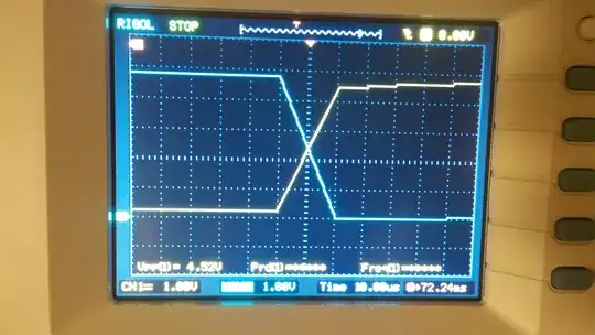
For a RS-485 Communication using a Maxim MAX3292 Driver, Full Duplex, 1/4 load unit (54 \$\Omega\$), 5 Mbps, with UTP 120 \$\Omega\$, standard cable, for each receiving unit I am thinking on a design placing two (equal) connectors, and making a tee directly in the PCB, connecting both to the Driver.
Being 10 Mbps the maximum realizable speed with this device, Should I consider a strip geometry as Power Divider, for matching impedances (\$\lambda\sim2m\$ for 70% VF) ? or a lumped parameters Power Divider like this (with 180pF, 90pF and 2.7uH)? Or an specific device|driver? Should I take some design cautions on this tee (angle, dimensions, lengths, details), or it is enough to simply draw a "T" and minimizing the vias quantity (see the referencial PCB sketch)?
Thanks in advance.
