10

Okay guys, I've been tasked with making a light-dimming control system for a 240V heat lamp dissipating around 250W. I need to adjust the heat output on the lamp by control from a microprocessor.

I'm developing on an 8051-based SoC with RF circuitry and some sensors and actuators. Basically it's a node in a wireless sensor network. I've left all other components out.

I'm mostly a software guy, so I might need some help here. Pardon my lingo and if I raise fundamental questions, I don't have a lot of experience with this.

I am thinking of a design like this for the dimmer circuit:

enter image description here

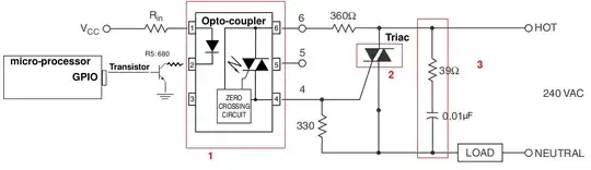
.. and I have some questions :) I've marked red boxes with numbers matching the questions:

1)

  • Is this a sensible way to drive a triac ? The resistor on pin 6 should have a higher power rating. Like 5W or something I would guess.
  • The GPIO leg can supply up to 500mA, so it should be plenty to drive the gate for the transistor right?
  • And mostly any transistor will do I take it.

2)

I don't know how inductive the heat lamp is, or how its resistance changes with temperature. I want to do an estimate of how the triac should be spec'd.

  • 240VAC(rms) would be ~340VAC(peak2peak), so 400V max isolation voltage should suffice, no?
  • A max surge-current rating of 4A would leave some overhead I would assume, but I'm not sure how much I need. I am assuming a switch-on from cold could draw a lot of current - should I instrument to be sure? I don't have any data on the heat lamp other than its rated for 250W max.

3)

  • Am I understanding correctly that this is the snubber?

I've found a couple of topics that helped me, but I'd appreciate a comment. I read these:

TL;DR: Am I way off with the schematic? Some help on guestimating the rating of the components would be nice as well :)

Morten Jensen
  • 966
  • 1
  • 8
  • 18
  • 1
    What is unique about your situation that prevents the use of a standard off-the-shelf timer switch? – Dave Tweed Oct 19 '12 at 14:42
  • Related question regarding the isolated zero-crossing detection: http://electronics.stackexchange.com/questions/17008/how-can-i-detect-a-power-outage-with-a-microcontroller | Other helpful questions: http://electronics.stackexchange.com/questions/28760/trouble-with-triac-driven-dimmer-circuit/ ; http://electronics.stackexchange.com/questions/18163/what-does-random-phase-means-in-a-triac-driver – m.Alin Oct 19 '12 at 14:50
  • @DaveTweed: I'm not sure I understand what you mean. I need to dim the light, not just switch it on/off. I am developing this as part of a product :) – Morten Jensen Oct 19 '12 at 16:31
  • What is unique about your situation that prevents the use of a standard off-the-shelf dimmer? – Dave Tweed Oct 19 '12 at 16:42
  • I'm not just being facetious; it sounds like all your requirements can be met by putting a standard dimmer in series with a standard timer switch. Why is someone going to buy your product instead? – Dave Tweed Oct 19 '12 at 16:49
  • @DaveTweed It seems quite obvious: He needs to build a dimmer using discrete components which will be part of a more complex final product; an off-the-shelf solution will probably be bulkier and maybe have extra components which aren't needed in this particular application. Which off-the-shelf dimmer/timer switch do you have in mind? – m.Alin Oct 19 '12 at 16:51
  • 1
    @DaveTweed: It is as m.Alin suggests. This is part of a larger design and not just a dimmer :) The design will be made in volumes of a couple thousands, so unit price has some priority. Though if you know of a dimmer I can use, please post a link :) – Morten Jensen Oct 19 '12 at 16:58
  • 1
    It all boils down to how the dimmer is to be controlled, and you're not giving us the context we need to determine that. Are you trying to regulate the temperature of something? You say that you're handling the zero crossing detection yourself, but you haven't shown us that. As far as the AC side of the circuit, what question do you have that isn't answered in the thousands of data sheets and application notes for triacs and optoisolators out there? – Dave Tweed Oct 19 '12 at 17:33
  • I suggest you to jump into the pool before criticizing it's hot or cool. As Dave suggested. – Standard Sandun Oct 19 '12 at 17:57
  • @sandundhammika: what am I criticizing :)? Dave, I've made you an edit – Morten Jensen Oct 19 '12 at 23:48
  • 1
    @MortenJensen , just never mind it too much. What I told you is if you double check for safety , then there's nothing more to check. If you new to AC power electronics, find somebody who is experienced to guide you. – Standard Sandun Oct 21 '12 at 16:04
  • 1
    Without the FULL schematic you are asking us to just guess. What you have shown right now is just the output stage; there is no way the SOC will be detecting a zero cross without additional circuitry. – akohlsmith Oct 24 '12 at 15:39
  • never use optocouplor with zero crossing in built it will give false triggring – Subhash Chandra Jun 30 '16 at 08:27

4 Answers4

5

First off if you are controlling a heating element you don't need a snubber.

Second, safe is a relative term. If by safe you are asking if it will explode and catch fire then build it an find out. If by safe you mean can I or anyone here tell you that you have built a safe circuit, meaning that you won't hurt someone.... well good luck getting a commitment there. 240 VAC is generally considered unsafe voltages to mess around with, so its not wise for anyone to give you the go ahead.

Here is a link that shows an application note that will help you design the circuit.

http://www.fairchildsemi.com/an/AN/AN-3003.pdf

Safety advice: One more comment, remember that you need to handle the peak voltage when specifying a part, and handling surges and overvoltage situations that can arise from the power company. So 240 VAC is the RMS value (average), and the peak is times the sqrt of 2, or 340 volts. So make sure you use a triac that can handle 600V for a 240VAC circuit.

Diego C Nascimento
  • 1,022
  • 1
  • 13
  • 26
Brian
  • 236
  • 1
  • 2
4

I'll add a few more things:

  • 500 milliamps is a lot of current, and should be more than enough to drive the opto-isolator directly unless the uC runs at a different voltage. Even then, you can probably use it as a sink.

  • If you still keep the transistor, you need a resistor between the GPIO and the base. B->E on a transistor operates like a diode, so it'll pull as much current as you let it, while only needing a few milliamps to do its job. Check the datasheets, but something like 1k should be plenty to do all the work you need to while not drawing excessive current.

  • Remember the operating behavior of a TRIAC when deciding to use it in this manner. It won't turn off until the AC voltage swings to the opposite polarity and crosses zero. This means you can't use PWM in the traditional sense as provided by the uC (since that's generally dozens of kilohertz), and will have to watch the zerocross yourself and count internally to trigger the triac. You may have simplified the diagram, but I didn't see anything to indicate that you are feeding the zero-cross signal into your uC.

Bryan Boettcher
  • 1,627
  • 1
  • 14
  • 20
1

i have started working with AC dimming of LED AC light bulbs and made this circuit which uses a 555 timer for the zero detection.

555 zero cross ac dimmerhttps://www.dropbox.com/s/l1mweybxcspuqwr/555.png?dl=0

i did not see the need for a snubber circuit until now. i started testing with longer (25m) cable between bulb and dimmer and saw a flicker.

not sure how important flicker is for your heating lamp.

you might have solved the problem already. would be great to hear who it went.

good luck.

1

Regarding safe voltages, it's good question. I see that the voltage swings in the mains are up to 260 VAC RMS; that's about 364 VAC peak. A 400 V TRIAC could just meet that requirements. However, it would be wise to use a 600 V TRIAC, but these are more costly.

m.Alin
  • 10,638
  • 19
  • 62
  • 89
Fran
  • 11
  • 1