2

I am using a USB D/A converter to drive a high-voltage op-amp with a signal between 0 and 3V at 10 kHz. The D/A I am using is capable of outputting between -10 and +10 and unfortunately seems to always output a 1 ms long glitch of -10.7V around 20-30 ms before the signal generation begins.

Although I am trying to get the vendor to supply a software fix, I want a hardware solution to ensure the output can't drop below 0V even in the event of a software glitch.

I am aware of diode clamping circuits but the lowest voltage Schottky I can find is 220 mV with the exception of a very strange diode that seems to have a built-in FET (SM74611), which I'm guessing is not meant for this application.

I would like to keep the output above -100 mV and preferably above -10 mV. Are there any other "passive" solutions I'm overlooking that could accomplish this or do I have to go with something active like an op-amp?

If active is the only way, can someone suggest a suitable circuit?
Kevin Morse
  • 123
  • 3
  • How close do you **need** to get to 0V? There has to be some margin between the two voltages. – Spehro Pefhany Jul 25 '19 at 23:48
  • @SpehroPefhany the high-voltage op-amp has a fixed gain of 65 so I could probably go as low as -10 or -20 mV without issue. I am just doing some calculations now. – Kevin Morse Jul 26 '19 at 00:00
  • @SpehroPefhany looks like I can actually go as low as -100mV into the op-amp without any danger of damaging anything. – Kevin Morse Jul 26 '19 at 00:09
  • Do you have to go all the way to zero? Are you okay with +50mV, say? – Spehro Pefhany Jul 26 '19 at 00:09
  • I have to get all the way to 0 but I could tolerate going a little below. – Kevin Morse Jul 26 '19 at 00:09
  • There is no way that you can change the negative supply of your D/A to 0V? What about a switch between the D/A and op-amp or an open collector/drain pull down transistr if the rectifiers does not suites your case? – Christian B. Jul 26 '19 at 21:27

1 Answers1

4

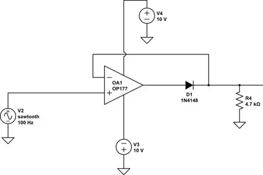
You could use a precision rectifier, something like the below circuit (you can modify the op-amp type as required, note the kink in the time domain where the op-amp recovers from saturation).

schematic

simulate this circuit – Schematic created using CircuitLab

enter image description here

This will get down to within uV of zero depending on the op-amp. If you need to go a bit lower, bias the top end of R4 with a suitable resistor to a negative source. Eg. a couple M ohms to -5 will allow it to go to -10mV.

If it's actually going to go below zero in normal operation and trigger the recovery from saturation you could find op-amps that recover faster (very few are actually rated for this operation) and/or you could use a different circuit such as this one:

schematic

simulate this circuit

There will still be a bit of distortion at the zero crossing because the op-amp output has to slew from -0.7V to +0.7V and that can't happen instantly, but there is no saturation.

Spehro Pefhany
  • 376,485
  • 21
  • 320
  • 842