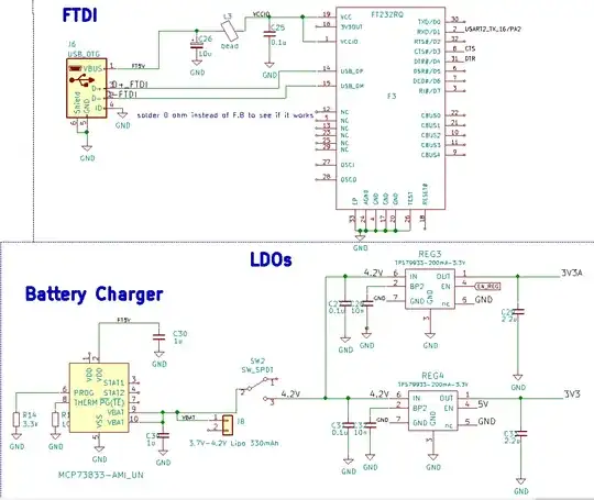
The answer by Bill dubuque was very helpful and got me to read the complete datasheet of MCP73831/2, but there is one thing from the datasheet that I don't fully understand and is the cause of lots of confusion I've been having with my circuit (see below).
 Assume that the switch is in position 3, closed circuit, for everything I'm discussing below.
For a long time I was wondering why the MCP73833 wouldn't provide 4.2 V at its output, when I apply 5V from a USB cable, if the battery is not connected. Instead, when powered with 5V at the input, the output of the battery charger is ~3.3V and the output of the regulators drops to ~2.8 V from the expected 3.3 V. Why couldn't I just remove the battery and let the Ireg current from the MCP73833 power the rest of the circuit? (Ireg defined by 1000(V)/Rprog(kOhm), in my case 1000/3.3k= 303mA ).
Well, after reading the datasheet (page 13, section 4.2) I believe I got closer to the truth. There is a feature called battery detection where a small 6uA current is sourced from the Vbat pin (output of the battery charger) and depending on whether the voltage rises to a certain threshold or falls below it, the IC will either not start the charge cycle or detect that a battery is there and begin charging.
A few lines below, the datasheet also mentions: "For a charge cycle to begin, all UVLO conditions must be met and a battery or output load must be present"
First question
Why isn't the rest of the circuit (the two LDOs) enough of a load so that even without the battery charging can begin, meaning current can be sourced?
Second question
Say Rprog is 3k and allows for a current of 1000/3k= 333 mA. That is almost exactly 1C, with the battery being 330 mAh.
a) How can simultaneous power and charging be achieved if there is no more current allowed by MCP73833 to power the rest of the circuit? Should I reduce Rprog to allow more current but exceed the recommended 1C, or can I assume that powering the circuit will take precedence over charging the cell? Nothing like that is stated in the datasheet of MCP73833.
b) If for whatever reason the IC is "smart" enough to power the rest of the circuit with some of the 333 mA, while the rest of the current charges the battery, how come then it can identify the two LDOs as this extra load that requires powering but earlier, without the battery connected, it coudn't detect it at all due to the battery detection feature?