5

Possible Duplicate:
How can I use a 12 V input on a digital Arduino pin?

I want to measure a car battery voltage (range is between 10-13v). But my AVR accepts analog inputs from 0-5v. How can I make the input voltage lower so I can measure the 3v voltage difference (10-13v) in around 1024 steps (0-5v from the microcontroller).

Basically I need a voltage step down converter that works linear, the ones I know only give out a fixed voltage (5-20v converts to 5v always like the 7805).

I don't want to use a voltage divider because then I can never get that 3v resolution I think.

Roger Far
  • 190
  • 7

3 Answers3

11

You can use a simple resistor divider to scale the 0..13 V down to 0..5 V.

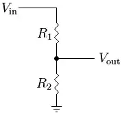
\$V_{out} = \dfrac{R_2}{R_1 + R_2} \cdot V_{in}\$

so that for \$R_1\$ = 16 kΩ and \$R_2\$ = 10 kΩ you get 0..5 V out for 0..13 V in.

That's the most simple solution, but it will map the 10..13 V to 3.85..5 V rather than to 0..5 V. The question is: do you really need the ADC's full range? A 10-bit ADC gives you a resolution of 13 mV for a 13 V input range. Do you really want to know the battery's voltage to 3 mV precise?

Anyway, if you do want to use the ADC's full range the solution is a difference amplifier, which subtracts a 10 V offset from the input voltage:

if \$R_1 = R_2\$ and \$R_f = R_g\$ then

\$ V_{out} = \dfrac{R_f}{R_1} \cdot (V_2 -V_1) \$

You apply a 10 V reference voltage to \$V_1\$ and connect the battery to \$V_2\$. Select 25 kΩ for \$R_f\$ and \$R_g\$, and 15 kΩ for \$R_1\$ and \$R_2\$, and you'll get 0..5 V out for 10..13 V in.

To use the full range down to 0 V out you'll need an RRIO (Rail-to-Rail I/o) opamp.


Note:
You can't use the optocoupler solution from the question I refer to here, since that is digital only. It saturates the output if the input voltage is present, and is by no means linear. If you want the input to be isolated from the output you can use a linear optocoupler, like the IL300 I refer to in this answer.

stevenvh
  • 145,145
  • 21
  • 455
  • 667
5

If your requirement could be relaxed somewhat, to translate the full-range ADC readout to 9-13 volts instead of 10-13, where you know your battery does not drop below 10V, this would work better: The ADC range below 10V be unused, but the difference amp suggested by @stevenvh would work reliably down to the 10 volt line.

A voltage reference IC or combination of zeners could be used for the 9v (or 9.5v if you insist) reference, as a 10V reference powered by the battery would likely get unstable or fail when the power rail actually hits 10v.

Similarly, it might be prudent to allow for a range slightly beyond 13 volts (mapped down to 0-5V for the ADC): During charging or temperature changes, the battery could hit a higher voltage than its nominal upper number.

Anindo Ghosh
  • 50,188
  • 8
  • 103
  • 200
1

Do you need 10-bit resolution or 10-bit acuracy?

To get 10-bit accuracy the 10V drop has to be >> 0.1% accurate, which is difficult to achieve. 0.1% resistors are not that hard to get, but once you calculate the accuracy of a TL431 or the various errors of an op-amp (and the 10V reference) into the equation you will probably end up with 1% rather than 0.1%. And don't forget you are probably measuring against your 5V supply as reference, which is probably a 7805 which is only 5% accurate.

If OTOH you need only 10-bit resolution a TL431 'programmable' zener could be used to subtract 10V from your input. Or go with steven's opamp summer, but for that you will need a stable 10V reference.

Wouter van Ooijen
  • 48,407
  • 1
  • 63
  • 136