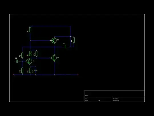
simulate this circuit – Schematic created using CircuitLab
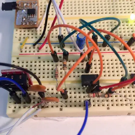
iagramI am attempting to create a high side switching circuit for a string of LEDs wired in parallel. There are multiple strings, all wired together, which share a common ground, so low side switching is not an option.
I have found a schematic for a high side switching network, which looks promising. However, I am unclear on how to determine the proper value of the resistors. Any help would be appreciated.
The intent is to control the circuit with a PWM signal from an Arduino, Rasberry Pi, or similar.