1

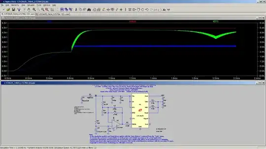
Trying out the LTspice simulator, to test a super capacitor charging circuit. With no load, its showing that its drawing 5A. Surely this cannot be correct?

LTspice simulation with LTC3625


Not there yet. Using the stock standard LTspice model for the LTC3625, with only one modification, changing the .ic V(out)=4.4 to .ic V(out)=0.0, to show how long it takes to charge the capacitors and reach the correct output, NOW it only reaches a max of VOUT 2.5V. Why?
enter image description here

Dave Tweed
  • 168,369
  • 17
  • 228
  • 393
  • what if you change your cell to a common voltage source? my first thought was that maybe it's "shunting" down excessive power from the cell. – user103776 Jun 10 '19 at 08:21
  • Your graph only shows the first 2 ms - try waiting several hundred ms to see if it settles down to some low value. – Andy aka Jun 10 '19 at 08:23
  • Thank you. yes it does settle down after 4ms with the small caps. But i wanted to see how long it takes with a fixed current source, i.e a small solar panel. – phantomrose1999 Jun 10 '19 at 08:58

1 Answers1

0

The supercapacitors in that simulation start out very-nearly charged. In fact the charging ends just after 4ms.

If you change the SPICE Directive .tran 4m to .tran 200m then you will simulate for 200ms and be able to see exactly what is going on.

To start the supercapacitors discharged just change the directive .ic V(out)=4.4 to .ic V(out)=0.

They have given that simulation a very beefy solar panel which is why the charging current is high. You can replace that solar panel model with your own quite easily; there is an excellent example here: https://electronics.stackexchange.com/a/257426/193946

Cursorkeys
  • 1,118
  • 7
  • 12
  • 1
    Thank you.. Yes i concluded the solar panel definition is not correct as i have a much smaller one and need to limit the input current to see how long it takes to fully charge the super capacitors. Rapidly learning LTspice. – phantomrose1999 Jun 10 '19 at 08:57
  • The PV is defined using the following directive, i can change the voltage by changing the V100 Line "5" twice. Is there any way to limit the current to 0.2A with this Directive ? .subckt PhotoCell B A C1 A B 1n V1 N001 B PWL 0 0 1m 5 2m 4 3m 5 D1 N001 A S2 R1 A N001 75 .model S2 D(Ron=.1 Ilimit=5.1 epsilon=.5) .ends – phantomrose1999 Jun 10 '19 at 09:38
  • My edits dont seem to have the CRLF on the end, looks fine when i type but its all one line when i save it. – phantomrose1999 Jun 10 '19 at 09:43