7

I've seen in a lot of projects a cool presentation of byte such as :

      Fuse high byte:  
      0xc9 = 1 1 0 0   1 0 0 1 -- BOOTRST (boot reset vector at 0x0000)  
             ^ ^ ^ ^   ^ ^ ^------ BOOTSZ0  
             | | | |   | +-------- BOOTSZ1  
             | | | |   + --------- EESAVE (don't preserve EEPROM over chip erase)  
             | | | +-------------- CKOPT (full output swing)  
             | | +---------------- SPIEN (allow serial programming)  
             | +------------------ WDTON (WDT not always on)  
            +-------------------- RSTDISBL (reset pin is enabled)  

or

    Fuse low byte:
     0x9f = 1 0 0 1   1 1 1 1
            ^ ^ \ /   \--+--/
            | |  |       +------- CKSEL 3..0 (external >8M crystal)
            | |  +--------------- SUT 1..0 (crystal osc, BOD enabled)
            | +------------------ BODEN (BrownOut Detector enabled)
            +-------------------- BODLEVEL (2.7V)

I wonder if anyone can tell me how, or where, I can make some of these ?

edit : I mean, I often see those type of presentation in texte format, so I suppose it isen't made by hand. I was hopping to find the software/url to generate the samme.

jojo l'abricot
  • 261
  • 3
  • 7

6 Answers6

5

That's a rather tedius way to show the fields in a binary number. Here is a snippet from actual source code that shows how I do it:

         setreg  b'00010000', eccp1as
                 ; 0-------  clear any existing shutdown event
                 ; -001----  shut down PWM on comparator 1 high
                 ; ----00--  P1A and P1C shutdown state is low
                 ; ------00  P1B and P1D shutdown state is low

         setreg  b'10000000', pwm1con
                 ; 1-------  auto restart once shutdown condition goes away
                 ; -0000000  no restart delay

         setreg  b'00000001', pstrcon
                 ; XXX-----  unused
                 ; ---0----  output pin steering takes effect immediately
                 ; ----0---  P1D pin not driven, has normal port function
                 ; -----0--  P1C pin not driven, has normal port function
                 ; ------0-  P1B pin not driven, has normal port function
                 ; -------1  P1A pin drive from PWM signal

I think this is easier than your elaborate example, but still shows the same information. Yes, I really do write code like this.

Olin Lathrop
  • 310,974
  • 36
  • 428
  • 915
5

You can play with something with graphviz and dot. Those are the tools doxygen uses to create the diagrams. It is not exactly what you are searching for, but it is fast and easy to script and the output is kind of nice looking (even thou it is a little hard to follow some lines...)


This example will generate something like this

alt text

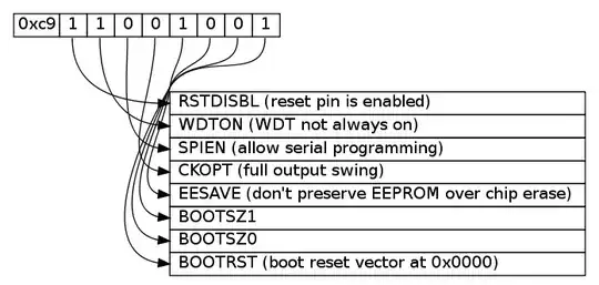
To do this you first create a file called byte.dot

digraph structs { 
node [shape=plaintext] 

struct1 [label=< 
<TABLE BORDER="0" CELLBORDER="1" CELLSPACING="0" ALIGN="left">  
    <TR>
        <TD>0xc9</TD>
        <TD PORT="f0"> 1 </TD>
        <TD PORT="f1"> 1 </TD>
        <TD PORT="f2"> 0 </TD>
        <TD PORT="f3"> 0 </TD>

        <TD PORT="f4"> 1 </TD>
        <TD PORT="f5"> 0 </TD>
        <TD PORT="f6"> 0 </TD>
        <TD PORT="f7"> 1 </TD>
    </TR> 
</TABLE>>]; 

struct2 [label=< 
<TABLE BORDER="0" CELLBORDER="1" CELLSPACING="0" >  
    <TR> <TD ALIGN="left" PORT="f0"> RSTDISBL (reset pin is enabled) </TD> </TR>
    <TR> <TD ALIGN="left" PORT="f1"> WDTON (WDT not always on) </TD> </TR>
    <TR> <TD ALIGN="left" PORT="f2"> SPIEN (allow serial programming)  </TD> </TR>
    <TR> <TD ALIGN="left" PORT="f3"> CKOPT (full output swing) </TD> </TR>

    <TR> <TD ALIGN="left" PORT="f4"> EESAVE (don't preserve EEPROM over chip erase)  </TD> </TR>
    <TR> <TD ALIGN="left" PORT="f5"> BOOTSZ1 </TD> </TR>
    <TR> <TD ALIGN="left" PORT="f6"> BOOTSZ0 </TD> </TR>
    <TR> <TD ALIGN="left" PORT="f7"> BOOTRST (boot reset vector at 0x0000) </TD> </TR>
</TABLE>>]; 

struct1:f0:s -> struct2:f0:w;
struct1:f1:s -> struct2:f1:w;
struct1:f2:s -> struct2:f2:w; 
struct1:f3:s -> struct2:f3:w;

struct1:f4:s -> struct2:f4:w;
struct1:f5:s -> struct2:f5:w;
struct1:f6:s -> struct2:f6:w; 
struct1:f7:s -> struct2:f7:w;
} 

Then run one of those commands.

dot -Tpng byte.dot -o byte.png 
dot -Tps  byte.dot -o byte.ps

Maybe it will be nicer if we do not cross all the lines in the middle?

alt text

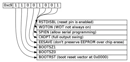
I just switched the named in the second table from f0..f7 into f7..f0.

<TABLE BORDER="0" CELLBORDER="1" CELLSPACING="0" >
    <TR> <TD ALIGN="left" PORT="f7"> RSTDISBL (reset pin is enabled) </TD> </TR>
    <TR> <TD ALIGN="left" PORT="f6"> WDTON (WDT not always on) </TD> </TR>
    <TR> <TD ALIGN="left" PORT="f5"> SPIEN (allow serial programming)  </TD> </TR>
    <TR> <TD ALIGN="left" PORT="f4"> CKOPT (full output swing) </TD> </TR>

    <TR> <TD ALIGN="left" PORT="f3"> EESAVE (don't preserve EEPROM over chip erase)  </TD> </TR>
    <TR> <TD ALIGN="left" PORT="f2"> BOOTSZ1 </TD> </TR>
    <TR> <TD ALIGN="left" PORT="f1"> BOOTSZ0 </TD> </TR>
    <TR> <TD ALIGN="left" PORT="f0"> BOOTRST (boot reset vector at 0x0000) </TD> </TR>
</TABLE>>];
Johan
  • 2,385
  • 2
  • 25
  • 27
4

In your favourite text editor. I can recommend vim.

Kevin Vermeer
  • 19,989
  • 8
  • 57
  • 102
Toby Jaffey
  • 28,796
  • 19
  • 96
  • 150
2

You could use Gliffy, an online package similar to Visio. I knocked out some of your diagram in about two minutes: http://www.gliffy.com/pubdoc/2237997/L.png

1

In the editor of Dos Navigator there is a special draw mode. You can enable double line drawing by pressing F4, then F4 again for single line, and again to disable. You can easily draw lines with the cursor keys while holding the shift key.

1 1 0 0   1 1 0 0 ───────┬┐
│ │   ║       ║ │        │├───────┐
│ │   ║       ║ └────────┴┘       │
│ │   ║       ║                   │
│ │   ║       ║                   │
│ │   ║       ║                   │
│ │   ║       ╚═════════════╗     │
│ │   ╚═════════════════════╝     │
│ │                               │
│ │                               │
│ └───────────────────────┬┐     ┌┘
│                 ┌┬┐┌┐  ┌┘└┐   ┌┘
└───────────────┐┌┤│││└┐┌┘  └┐ ┌┘
                └┘└┘└┘ └┘    └─┘
csadam
  • 1,626
  • 2
  • 16
  • 24
  • 2
    Emacs Artist mode does that sort of thing too, without resorting to non-ASCII symbols. I still simply type these things, though overwrite, free placement and repetition commands can help. – Yann Vernier Oct 16 '10 at 13:36
0

ditaa does what your'e looking for. The following image is generated from your raw text above.

alt text

Might need a bit of editing to get the formatting right...

J. Polfer
  • 3,780
  • 2
  • 27
  • 33
  • 1
    Know what? This isn't what the OP is looking for, despite its coolness. He wants something that will generate ASCII art for him... I can't downvote my own post... – J. Polfer Dec 10 '10 at 18:52