0

I have a control voltage signal of an audio synthesizer that goes from +15v to -15v and I want to scale it into +10v to -5v.

I want to scale its range.

How can I do that?

I guess a way to do it is offsetting the ground to +2.5v and then dividing the incoming signal by 2. But, is there a neater way to do it?

Irene Nesser
  • 23
  • 1
  • 6
  • 1
    You'll need to add more info about what your signal is and what sink it is driving. How strong is the source of the signal (can it drive a low impedance sink). Is your sink high impedance or low impedance? By clamp do you mean clip any voltage outside your range, or do you want to scale the input signal to the range? – Tom Carpenter May 31 '19 at 08:15
  • It's the Control Voltage signal of an audio synthesizer. – Irene Nesser May 31 '19 at 08:23
  • 4
    "Scaling" and "clamping" are two different things. "Scaling" makes your control signal fit the given range - the scaled signal always represents the original signal. "Clamping" cuts off values that are out of range - the clamped signal doesn't always follow the original. Which do you really need? Scale (make all values fit the allowed range?) Or clamp (discard values outside the allowed range?) – JRE May 31 '19 at 08:43
  • I need to scale it. – Irene Nesser May 31 '19 at 09:44
  • But the scale is not symmetrical relative to ground, as you can see. – Irene Nesser May 31 '19 at 10:16
  • You scale the range (+15 to -15) to +- 7.5V, then add 2.5V to the result. – JRE May 31 '19 at 10:59
  • Possible duplicate of [Combined ADC scaling and offset with variable input voltage ranges](https://electronics.stackexchange.com/questions/22742/combined-adc-scaling-and-offset-with-variable-input-voltage-ranges) – JRE May 31 '19 at 11:02
  • I've voted to close your question as a duplicate. This is a common question, and there are many questions and answers about it. [This answer seems to me to be quite detailed about how to go about it.](https://electronics.stackexchange.com/a/22760/47070) – JRE May 31 '19 at 11:05
  • It is the same task you are facing. It doesn't matter in the least that the other question is about feeding into an ADC and yours is about a VCO control signal. The concept and the process are the same. Scale and offset. – JRE May 31 '19 at 11:07
  • Take the information there, or in other similar questions. Make your best attempt at implementing it. When you have something, you can ask a new question to have someone verify your results. Or, if you get stuck following those other answers, start a new question and explain what you were doing (which answer you were following) and where you got stuck. Show your partial results, and explain why you are stuck. – JRE May 31 '19 at 11:10
  • It can't be done mathematically any other way, so the circuit has to do the same. You can probably do it with a single opamp, but that's about all the simplification you can expect. – JRE May 31 '19 at 11:27
  • Thank you. You have been really helpful. – Irene Nesser May 31 '19 at 11:31

1 Answers1

2

Schematic:

Solution using 1 Op. Amp.

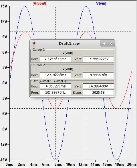
LTSpice Simulation:

Input / Output

Calculations:

R5 = R7 (For gain = 1) = 10k (Reasonable common value)

R3 || R4 = R1 || R2 = 10K (For equal equiv. resistors, gain = 1, no DC gain)

15 * R4 / (R3 + R4) = 2.5 (For the voltage offset)

R1 = R2 (To divide input by 2)

devnull
  • 8,447
  • 2
  • 15
  • 38