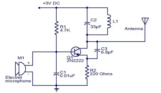
I designed a simple class D amplifier based on theory (output stage not pictured):
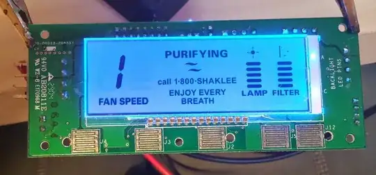
Layout(ish, the board was modified in a few places, the whole top part is a separate PCB soldered into where some really bad design was dremeled out):
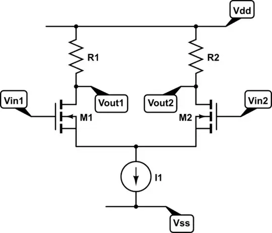 The IC not on the schematic is LTC3261.
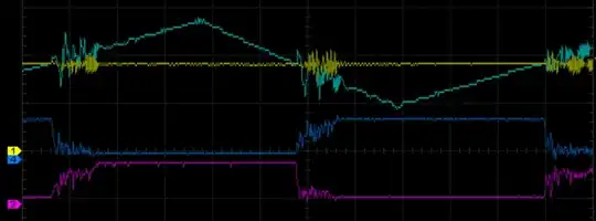
After assembling it I measured the inputs and outputs of the comparator with an oscilloscope and noticed some unexpected oscillations:
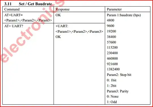 1 is -, 2 is +, 3 and 4 are the outputs.
What causes those? How should I eliminate them?
EDIT: I added a 470K feedback resistor which partially solved the problem (accidentally swapped channels 1 and 2):
 Is there anything else I should try?
EDIT2: I accidentally found out the ringing is gone when measuring only the outputs (with no resistor added) indicating the oscilloscope is at fault somehow? Shouldn't the 13pF capacitance be too small to cause such a strong effect?
