8

I have this stepper motor with unknown back EMF / RPM. There are 200 steps/rev (i.e. 1.8deg step angle), and 8mH "phase inductance", but I'm not sure if that's enough to calculate back EMF.

I hooked up one of the parallel windings from each phase to an oscilloscope. (Specifically, red/yellow on one probe, white/orange on the other probe.)

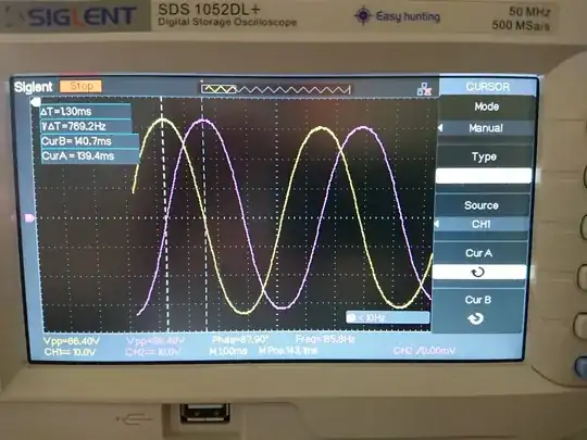
I then manually rotated the shaft and captured the following measurement. You can see that the time between two signal peaks is ~770Hz and the voltage magnitude is ~33V.

  • Do those two 90deg-phased peaks correspond to one step each, therefore implying that the RPM at that time was 770(step/sec) / 200(step/rev) * 60(sec/min) = 231RPM?
  • Does that imply that the back EMF is 33V/231RPM = 143mV/RPM?
  • If so, how is that reconciled with the specs saying 30VDC is sufficient to drive the stepper at 1500RPM, which would then correspond to ~214V in back EMF?

I'm a bit confused. If the motor was hooked up in "serial" mode instead, that would result in an even "worse" (double) back EMF/RPM.

stepper back emf


Edit: FYI, in case anyone thinks this is because there is no load attached, I applied a 22 Ohm resistor to one of the parallel winding terminals, performed a similar measurement and calculated a similar back EMF constant of 134mV/RPM (compared to 143mV/RPM earlier). So I don't think it has to do with the terminals being "open circuit" (which they technically wouldn't be anyway, since the scope probe or air has a very large but still not infinite resistance).


Edit 2: This question is similar and seems to support my back emf constant measurement method. However, that person was also encountering an unexpected value, and no satisfying answer was given.


Edit 3: I should add, my calculated back EMF / RPM was based on the sinusoidal peak vs the average (which it should be according to this answer). Therefore, to make my calculated back EMF constant above consistent with the usual definition, it should be multiplied by 2/pi ~= .637. However, even 64% of the calculated voltage at 1500 RPM is still way above the 30V I was expecting to be able to use.
abc
  • 619
  • 6
  • 21
  • 1
    The no-load voltage is like the no torque voltage which could never hold any position. – Tony Stewart EE75 May 12 '19 at 15:53
  • @SunnyskyguyEE75 Okay, so I guess you're saying that the back EMF of floating leads could be very high relative to the driving voltage, but that it's ineffectual in practice because it will get quickly "burned off" by the opposing driving voltage? – abc May 12 '19 at 16:01
  • In order to do work there must be some torque at speed due to excess voltage drive above BEMF – Tony Stewart EE75 May 12 '19 at 16:02
  • 2
    That certainly goes directly against what I understand of how motors work. Given that it's a stepper, though, I'm a bit out of my experience. I would try two things. First, the measured value seems to be about 10x what it would be for the motor rating, and on some oscilloscopes it's easy to get the probe setting wrong and read 10x too high -- so I'd check that. If I'm feeling particularly slow, I'll grab a 1.5V or 9V battery and measure that as a check. Second, try loading the coil with a modest resistance (1k-ohm?) and measure again -- there may be some weird stepper-thing going on. – TimWescott May 12 '19 at 16:15
  • @TimWescott Okay, thanks for the input -- I also did not understand motors to work that way either. I did verify that my probes were set up properly by hooking up a 30V bench supply. This is a hefty stepper motor (~10lbs), so I guess I'm not too surprised by the large magnitudes I'm seeing. I can try adding a load, but I'm not sure how helpful that would be, as in practice the motor leads are not hooked up to a load, and essentially have a direct path to the supply rails. AFAIK, a stepper is basically like any other BLDC motor, but just with a much higher pole count. – abc May 12 '19 at 16:38
  • Actually, just hooked it up to a small load, and I can guarantee that's not going to help things. That's basically just braking the motor, albeit with a weaker effect than if the terminals were shorted without a load. – abc May 12 '19 at 16:41
  • OK. This is certainly weird. Now I'm down to thinking it's a resonance at 770Hz (which would have me rotating the thing at different speeds), or the cogging of the motor varying the speed as I turn it by hand (which would have me tearing my hair out). – TimWescott May 12 '19 at 16:48
  • R/L ratio f-3dB= 20 Hz so at 186 Hz the coil current is -20dB – Tony Stewart EE75 May 12 '19 at 16:54
  • 1
    Bipolar voltage of 30V is 60Vpp – Tony Stewart EE75 May 12 '19 at 17:40
  • Drive the motor (normally) at a known speed and measure a phase voltage when that phase is unenergised. – Chu May 12 '19 at 17:42

1 Answers1

4

This is a big stepper motor. The motor inductance of 8mH per phase is an indicator that is made to be used with high voltage stepper driver, like 325 VDC or 230VAC rectified, with a chopper driver, that has a current setpoint.

Have a look for similar model: Sanyo Denki

enter image description here

It has near 4mH per phase, similar to yours if you connect 8mH phases in parallel and it has 0.46 ohm per phase, similarly yours have 0.9 per phase, but connected in parallel gives 0.45 ohm. With a BEMF constant of 161V/kRPM you can expect similar torque characteristics also from yours motor.

At 140 VDC supply it has a knee point at 1200 rpm

At 48 VDC this drops to a 300 rpm

EDIT:

143mv/RPM is :

$$\require{cancel}\dfrac{143mV\cdot min}{R} =0,143V \dfrac{\bcancel{2\pi\ rad}\cdot 60s\cdot\bcancel{ min}}{2\pi\ rad\cdot\bcancel{ 60s}\cdot\bcancel{R}} = 1.366 \dfrac{V\cdot s}{rad} $$

$$k_t \approx 1.366\ Nm/A$$

While this doesn't hold for your motor : 1.366*6= 8.1Nm, it holds for Sanyp Denki motor. 0.161V/RPM = 1.54 Vs/rad; 1.54 Nm/A * 6A = 9.2 Nm.

Marko Buršič
  • 23,562
  • 2
  • 20
  • 33
  • Okay, so you're saying the calculated back EMF constant is correct, and 30V is nowhere near enough voltage to drive the stepper at 1500 RPM despite the specs appearing to say so? Maybe they intended for the 30V to feed one of their controllers which does a large step-up, but I kind of doubt it. I'll get in touch with the vendor. Thanks. – abc May 15 '19 at 13:08
  • Also, you're saying that back EMF amplitude can technically be higher than the driving voltage, and the driver can still successfully turn the motor forward (at diminished torque)? It sounds like the crossover point where the back EMF amplitude exceeds the DC supply voltage is at the "knee" you refer to. I guess somehow the driving voltage is injecting enough "forward current" to suppress current induced by the back EMF? – abc May 15 '19 at 14:36
  • Was that really only 60 RPM at 33 Vp? – Tony Stewart EE75 May 17 '19 at 00:55