9

I'm building a serial servo controller to learn about electronics and assembly language as part of my hexapod robot project. Quite early on I decided that I needed more I/O channels than my ATTiny2313 that I was using at the time supported so I investigated some 3-8 line demultiplexer chips (CD74HCT238E's) which have allowed me to create a 64 channel PWM servo controller with just 8 I/O pins for the PWM channels and 3 address lines.

Anyway. I also bought some CD74HCT138E's which are active low rather than the active high CD74HCT238E's. I understand, in principal, the differences between the current sourcing chip that I'm using and the current sinking chips but I don't really know how to adjust my circuit to use the current sinking chips instead of the current sourcing chips.

The schematic for the active high chips is here: alt text 
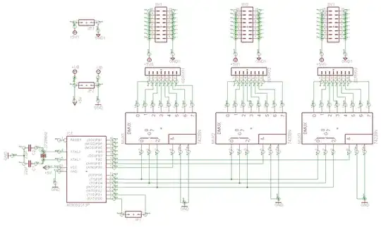
What do I need to change to swap the CD74HCT238E's for CD74HCT138E's?

Note that the reason for asking this question is that I bought a tube of the active low ICs by mistake and I'm curious at how much more complex the schematic and circuit design would need to be for me to make use of them.

Glorfindel
  • 1,245
  • 3
  • 15
  • 20
Len Holgate
  • 1,078
  • 1
  • 10
  • 19

2 Answers2

3

They are the same thing excluding the output. The active low is exactly the same as the active high with an inverted input on all pins.

I have a few app's with servos, this would require I put an inverter on each path or changed out my servos. With info for your servo I might be able to help more but I doubt this change is worth it.

I took a look through your site, I have enjoyed it both times I have visited it, but I did not find more hardware information, if I missed anything, I apologize. -Max Murphy

Kortuk
  • 13,362
  • 8
  • 60
  • 85
  • 2
    Yes, I realise they're the same except for the output. I assumed that there was a reasonably easy way to wire the servo to the active low IC. The servos are simple Hitec HS-422s. If I were to run a wire from VCC, via, I assume, a resistor, to the active low output pin then I assume that nothing would flow unless the pin is pulled low? – Len Holgate Nov 15 '09 at 09:55
  • 1
    I am not completely sure I understand your question, you are correct, your device will not pull current from a pull-up resistor when its output is high. The gate of the servo will pull current though the resistor and/or from your high output, probably both. It is still going to be high for the exact opposite duty cycle. Before if you were doing a duty cycle of 5% and now a duty cycle of 95%. The data sheet at http://www.robotshop.us/PDF/Servomanual.pdf, or I should say product guide, gives great information. Your pulse time with a specific off time in important. – Kortuk Nov 15 '09 at 10:40
  • 1
    Why do you need to change chips to Active Low? – Kortuk Nov 15 '09 at 10:40
  • 2
    I don't, I just bought a tube of them by mistake and want to know if it's possible. I've seen a design for a similar design of servo controller that uses what (from the data sheet) seemed to be active low ICs and I was curious :) – Len Holgate Nov 15 '09 at 11:51
  • 1
    Ahh, I am sorry, I was trying to stop you from changing designs, do you have the other design? You really just need to put inverters in, if you do not mind the space, it can be done with a transistor and a resistor. – Kortuk Nov 15 '09 at 11:55
2

The '238 have only one of eight outputs logic high, sourcing current, the rest of the pins will be logic low, sinking current. The '138 is precisely the opposite, one of eight pins can be low, sinking current, the rest will be high, sourcing current.

To "invert" the function of the '138, you could use eight PNP transistors with the bases each tied to an output of the '138 with a resistor, the emitters all connected to +5 and the collectors each connected to one of your servo connectors. Or use a bunch of inverters (74HCT04 or octal 74HCT240) to change the sense of the outputs.

Your choice of 1 of 8 decoders will limit what you can do with your servos, as your circuit can only activate one output at a time. Max speed of any one servo will be limited by the number of servos that you want active. If you wanted all 64 channels on, for example, they would all be running at at average of 1/64th speed.

The PCF8575C is very handy for expanding digital IO using serial I2C protocol from devices like Arduino. You could run 64 servos using 2 pins on the Arduino and 4 PCF8575Cs. This would give you more flexibility in setting your PWM duty cycles.

  • I'm getting the feeling that if I were using these chips to expand I/O for a reason other than servo control then swapping the active high for active low would be less of an issue, since I'd just reverse the circuit that I was connecting to the pin. However, since I need to drive the servo control line with +VE I need the inverters to give that to me as I can't drive the control line from somewhere else and simply sink it into the IC. – Len Holgate Nov 16 '09 at 10:03
  • As an aside, the PWM servo control using the active high ICs is working nicely. I run 8 of the 1 of 8 decoder chips off of my microprocessor and then cycle through the address lines (changing them every 2.5ms) so that I can generate the required 50Hz refresh on all 64 channels. This allows me to generate the required 600us-2.4ms pulses on each channel. I assume the PCF8575C is easier to use because you just send it a command to turn the appropriate pin on/off and it stays that way rather than the 238's needing the corresponding pin on the microprocessor to be held high for the duration. – Len Holgate Nov 16 '09 at 10:09
  • 1
    It really depends on application, I am glad to hear it is working. In many cases the chip you are hooked to is easy to deal with the change of active high to active low, but yours was not one of those. – Kortuk Nov 16 '09 at 12:10