45

I am creating a controller for a 12 V system using an Arduino Uno microcrontroller. For the outputs I am using a relay shield to switch the 12 V components. I have a 12 V toggle switch that turns on some 12 V components in the system and I want to use a trigger signal off of this same switch to send to an Arduino digital input. I know that the Arduino can only handle 5 V max. What would be the best way to step down the 12 V coming off of the switch to the 5 V for the input?

EDIT: The system is for use in a car. Would the amperage of the car battery need to be lowered somehow as to not blow up the components?

m.Alin
  • 10,638
  • 19
  • 62
  • 89
D.W.
  • 623
  • 1
  • 6
  • 9
  • 4
    the amperage of the car is irrelevant - the components only use as much current as they need. The car battery is capable of supplying hundreds of Amps, such as that needed for the starter motor. This doesnt mean there is always hundreds of amps flowing and could damage things. :) – KyranF Aug 06 '14 at 15:14

5 Answers5

52

Good news! This going to be cheap! :-)

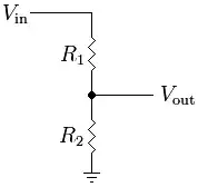
A simple resistor divider will bring the 12 V down to the 5 V an Arduino can digest. The output voltage can be calculated as

\$ V_{OUT} = \dfrac{R2}{R1+R2} V_{IN}\$

Resistor values in the range of 10 kΩ are a good choice. If your R2 is 10 kΩ then R1 should be 14 kΩ. Now 14 kΩ is not a standard value, but 15 kΩ is. Your input voltage will be 4.8 V instead of 5 V, but the Arduino will see that still as a high level. You also have a bit of headroom in case the 12 V should be a bit too high. Even 18 kΩ will still give you a sufficiently high 4.3 V, but then you have to start thinking about the 12 V a bit too low. Will the voltage still be seen as high? I would stick with the 15 kΩ.

edit
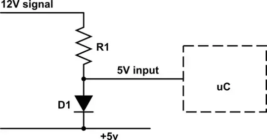
You mention an automotive environment, and then you do need some extra protection. The car's 12 V is never quite 12 V, but most of the time higher, with peaks several volts above the nominal 12 V. (Actually nominal is more like 12.9 V, at 2.15 V per cell.) You can place a 5 V zener diode in parallel with R2, and this should cut off any voltage higher than the zener's 5 V. But a zener voltage varies with the current, and at the low input current the resistors give you it will cut off at lower voltages. A better solution would be to have a Schottky diode between the Arduino's input and the 5 V supply. Then any input voltage higher than about 5.2 V will make the Schottky diode conduct, and the input voltage will be limited to the 5.2 V. You really need a Schottky diode for this, a common P-N diode has a 0.7 V drop instead of the Schottky's 0.2 V, and then the 5.7 V maximum input voltage may be too high.

Better
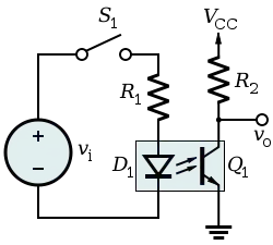
Michael's optocoupler is a good alternative, though a bit more expensive. You often will use an optocoupler to isolate input from output, but you can also use it to protect an input like you want here.

enter image description here

How it works: the input current light the internal infrared LED, which causes an output current through the phototransistor. The ratio between input and output current is called CTR, for Current Transfer Ratio. The CNY17 has a minimum CTR of 40 %, which means you need 10 mA input for 4 mA output. Let's go for the 10 mA input. Then R1 should be (12 V - 1.5 V) / 10 mA = 1 kΩ. The output resistor will have to cause a 5 V drop at 4 mA, then that should be 5 V / 4 mA = 1250 Ω. It's better to have a bit higher value, the voltage won't drop more than 5 V anyway. A 4.7 kΩ will limit the current to about 1 mA.

Vcc is the Arduino's 5 V supply, Vout goes to the Arduino's input. Note that the input will be inversed: it will be low if the 12 V is present, high when it isn't. If you don't want that, you can swap the position of the optocoupler's output and the pull-up resistor.

edit 2
How doesn't the optocoupler solution solve the overvoltage issue? The resistor divider is ratiometric: the output voltage is a fixed ration of the input. If you have calculated for 5 V out at 12 V in, then 24 V in will give 10 V out. Not OK, hence the protection diode.

In the optocoupler circuit you can see that the right side, which connects to the Arduino's input pin doesn't have any voltage higher than 5 V at all. If the optocoupler is on then the transistor will draw current, I used 4 mA in the example above. A 1.2 kΩ will cause a 4.8 V voltage drop, due to Ohm's Law (current times resistance = voltage). Then the output voltage will be 5 V (Vcc) - 4.8 V across the resistor = 0.2 V, that's a low level. If the current would be lower the voltage drop will be smaller as well, and the output voltage will rise. A 1 mA current, for instance, will cause a 1.2 V drop, and the output will be 5 V - 1.2 V = 3.8 V. The minimum current is zero. Then you don't have a voltage across the resistor, and the output will be 5 V. That's the maximum, there's nothing there which will give you a higher voltage.

What if the input voltage would become too high? You accidentally connect a 24 V battery instead of 12 V. Then the LED current will double, form 10 mA to 20 mA. The 40 % CTR will cause 8 mA output current instead of the calculated 4 mA. 8 mA through the 1.2 kΩ resistor would be a 9.6 V drop. But from a 5 V supply that would be negative, and that's impossible; you can't go lower than 0 V here. So while the optocoupler would very much like to draw 8 mA, the resistor will limit that. The maximum current through it is when the full 5 V is across it. The output will then be really 0 V, and the current 5 V / 1.2 kΩ = 4.2 mA. So whatever power supply you attach the output current won't go higher than that, and the voltage will stay between 0 V and 5 V. No further protection needed.

If you expect overvoltage you'll have to check if the optocoupler's LED can handle the increased current, but the 20 mA will not be a problem for most optocouplers (they're often rated at 50 mA maximum), and besides, that's for double input voltage, which probably won't happen IRL.

stevenvh
  • 145,145
  • 21
  • 455
  • 667
  • The system is for use in a car. Would the amperage of the car battery need to be lowered somehow to so as to not blow up the components? I am new at this. Thanks – D.W. Oct 12 '12 at 14:29
  • @D.W. Uh-oh, car! :-(. I'll update my answer. – stevenvh Oct 12 '12 at 14:30
  • @D.W. - No, the car battery's capacity doesn't matter. The current will be determined by the voltage (12 V) and the resistance (25 kohm in total). Then according to **Ohm's Law** the current will be 12 V / 25 kohm = 0.5 mA. It doesn't matter if the battery is a 40 Ah type or a 400 Ah type; the resistors won't allow more. – stevenvh Oct 12 '12 at 14:41
  • Thats great. Thanks for your help. Just curious but would something like this work? http://www.robotshop.com/ca/productinfo.aspx?pc=RB-Spa-750&lang=en-US – D.W. Oct 12 '12 at 15:55
  • @D.W.: with the opto-coupler you can keep the battery separated from the Arduino, but if it is powered from the battery both grounds will be connected. – Federico Russo Oct 12 '12 at 15:57
  • @D.W. - Yeah, seems fine. The same product can be found on the [Sparkfun site](https://www.sparkfun.com/products/9118), where there's more information, like a link to the optocoupler's datasheet. You get 2 channels, you could use the other one to sense another switched voltage if needed. – stevenvh Oct 12 '12 at 16:06
  • @D.W. - You're welcome. I was just thinking: do I need to add to my answer why the optocoupler is fine with a higher voltage, where the divider needed extra protection, or is that clear? Just ask if you need extra information. (Just don't ask money ;-)) – stevenvh Oct 12 '12 at 16:46
  • @stevenvh Maybe if you dont mind as I am completly new to this amazing world of electronics. I am a Mechanical Technologist and we hardly touched anything with electrical in college let alone electronics. Thanks – D.W. Oct 12 '12 at 17:07
  • @stevenvh Also just a quick question: The Arduino Uno manual says that the recomended input voltage is 7-12V and limits are 6-20V. Does that mean I can run it straight off of a the Car Battery? Thanks – D.W. Oct 12 '12 at 17:20
  • @D.W. - A car's 12 V can be extremely noisy, and may have high spikes on it. To protect the Arduino's voltage regulator against these you can place a [TVS](http://en.wikipedia.org/wiki/Transient_voltage_suppression_diode) (Transient Voltage Suppressor diode) across the Arduino's power input. – stevenvh Oct 12 '12 at 17:37
  • 2
    @stevenvh Thanks Steve. I look forward to returning to favor to someone that is new at electronics once I am confident with it. Thanks – D.W. Oct 12 '12 at 18:00
  • Another note: many 5V devices' logical HIGH input value is something much lower than 5V -- the PIC I'm using requires only 2V to read a logic 1. So using a simple voltage divider with, say, 4.7K and 1.8K resistors will drop 12V to 3.3V. If you perchance get voltages up to 18V, the input to your pin will still be just below 5V. – thirtythreeforty Mar 14 '15 at 18:38
  • @stevenvh thanks for that extensive answer. I was wondering if I could go with a [following](http://imgur.com/v1LdKym) circuit if I want a HIGH output for HIGH input (12V as well here but not a car :) ) The X1 connects to GND when button is pressed, Y1 is to Arduino pin. – bcelary Mar 25 '16 at 15:45
  • Lol, electronics.. makes programming look really easy! – John Hunt Aug 16 '17 at 13:54
  • Since you have rounded-up all choices here, [there is an opinion](https://forum.arduino.cc/index.php?topic=153143.0#msg_1148863), that you just might limit the current and let AVR's clamping protection diode keep the voltage at bay. It's suggested a simple resistor of 47k - 100k in series should do that. Seems like your schottky option, but without the external schottky. Or not? Would you consider this a valid option? – papo Aug 27 '19 at 04:28
  • also your own post here :) https://electronics.stackexchange.com/a/35817/180863 so I guess that answers the question. – papo Aug 27 '19 at 04:35
17

A good way to isolate the 12V switch signal would be to pass it through an opto coupler. The circuit would be configured similar to the following.

enter image description here

Vi in the diagram represents the 12V in your circuit that is switched by your switch (S1). Select R1 to limit the current through the D1 part of the opto coupler to a level that is within the ratings of the component that you select.

Opto couplers are not the fastest components in the world, especially the cheapest ones, but for the case of a slow action like a human controlled switch, the speed of the coupler is of little concern.

boardbite
  • 4,892
  • 11
  • 47
  • 73
Michael Karas
  • 56,889
  • 3
  • 70
  • 138
16

For voltage independency, use a resistor to regulate the current and a Zener to regulate voltage, like this:

schematic

simulate this circuit – Schematic created using CircuitLab

With a 30k resistor, this will output 4.99V and use only about 234uA @ 12Vin.
In this case:
R1 is consuming 234uA x (12V - 4.99V) = 1.64mW
D1 is consuming 234uA x 4.99V = 1.17mW

Total power consumption: 2.81mW (when input is high)

cyberponk
  • 662
  • 6
  • 10
  • For anything visible I would use LED + resistor divider in series to give a 5V signal at 12V and put the zener diode in parallel with the lower half of the divider and LED to protect against overvoltage. That way the LED lights up when you have an input signal and gives visual feedback. – Goswin von Brederlow Nov 29 '18 at 13:00
  • @GoswinvonBrederlow can you please draw the circuit led/diode/resistor circuit out? – sizzle Feb 12 '19 at 05:54
  • In the above schematic set R1 to 770 Ohm and add a 330Ohm and a red LED in parallel to the Zener diode. Then at 12V input ~9mA will flow through the LED and you get a 5V output signal. If the input voltage goes up though the zener diode will limit the output signal to 5.1V and protect both the arduino and the LED. – Goswin von Brederlow Feb 14 '19 at 11:41
15

You can also use a diode and a resistor, as follows:

schematic

simulate this circuit – Schematic created using CircuitLab

I'd make the resistor something fairly stiff, otherwise you'll be sinking a lot of power from this circuit. The beauty of this circuit (in comparison to the voltage divider) is that it doesn't care about whether your original voltage is 12V, 14V, or 15V: it will be 5V (actually 5.2-5.3V depending on the diode) regardless of the input voltage.

angelatlarge
  • 3,611
  • 22
  • 37
  • that's quite clever, +1 for voltage independency! – Florian Castellane Jan 14 '17 at 23:44
  • 6
    Careful with the overvoltage on pin absolute maximum rating. For example, ATmega32u4 datasheet: Voltage on any Pin with respect to Ground(8): -0.5V to VCC+0.5V. If using a regular diode, voltage will be greater than VCC + 0.5V if using anything less than 170kOhm resistor. I think Schottky diodes are the safest for this. – cyberponk Jan 24 '17 at 05:17
  • You should only do this with a Schottky diode. Otherwise the high side ESD diode in the uC will potentially enter conduction before D1 does. They aren't meant for continuous operation. – KevinThibedeau Jul 10 '21 at 17:30
-1

A little late but in my car i use the LM7805. Works great and is cheap.

  • 2
    Not as cheap as 2 resistors or a resistor and a diode. – Dave Tweed Dec 30 '15 at 16:03
  • 8
    @TonNies You got the question wrong. OP is not in search for a supply voltage for his controller. It's more about signal conditioning. – Ariser Dec 30 '15 at 17:22
  • 3
    Nothing wrong with using LM7805 for level shifting 12v signals. – chugadie Jul 29 '16 at 00:19
  • 2
    @chugadie: But a very uncommon and relatively "expensive" overkill approach if all you want is to bring 12V down for one IO pin. – Rev Feb 07 '17 at 07:43