I'm completely new to the world of FPGA's and thought I'd start with a very simple project: a 4-bit 7-segment decoder. The first version I wrote purely in VHDL (it's basically a single combinatorial select, no clocks necessary) and it seems to work, but I'd also like to experiment with the "IP Cores" stuff in the Xilinx ISE.
So for now I'm using the "ISE Project Explorer" GUI, and I created a new project with a ROM core. The generated VHDL code is:
LIBRARY ieee;
USE ieee.std_logic_1164.ALL;
-- synthesis translate_off
LIBRARY XilinxCoreLib;
-- synthesis translate_on
ENTITY SSROM IS
  PORT (
    clka : IN STD_LOGIC;
    addra : IN STD_LOGIC_VECTOR(3 DOWNTO 0);
    douta : OUT STD_LOGIC_VECTOR(6 DOWNTO 0)
  );
END SSROM;

ARCHITECTURE SSROM_a OF SSROM IS
-- synthesis translate_off
COMPONENT wrapped_SSROM
  PORT (
    clka : IN STD_LOGIC;
    addra : IN STD_LOGIC_VECTOR(3 DOWNTO 0);
    douta : OUT STD_LOGIC_VECTOR(6 DOWNTO 0)
  );
END COMPONENT;

-- Configuration specification
  FOR ALL : wrapped_SSROM USE ENTITY XilinxCoreLib.blk_mem_gen_v7_2(behavioral)
    GENERIC MAP (
      c_addra_width => 4,
      c_addrb_width => 4,
      c_algorithm => 1,
      c_axi_id_width => 4,
      c_axi_slave_type => 0,
      c_axi_type => 1,
      c_byte_size => 9,
      c_common_clk => 0,
      c_default_data => "0",
      c_disable_warn_bhv_coll => 0,
      c_disable_warn_bhv_range => 0,
      c_enable_32bit_address => 0,
      c_family => "spartan3",
      c_has_axi_id => 0,
      c_has_ena => 0,
      c_has_enb => 0,
      c_has_injecterr => 0,
      c_has_mem_output_regs_a => 0,
      c_has_mem_output_regs_b => 0,
      c_has_mux_output_regs_a => 0,
      c_has_mux_output_regs_b => 0,
      c_has_regcea => 0,
      c_has_regceb => 0,
      c_has_rsta => 0,
      c_has_rstb => 0,
      c_has_softecc_input_regs_a => 0,
      c_has_softecc_output_regs_b => 0,
      c_init_file_name => "SSROM.mif",
      c_inita_val => "0",
      c_initb_val => "0",
      c_interface_type => 0,
      c_load_init_file => 1,
      c_mem_type => 3,
      c_mux_pipeline_stages => 0,
      c_prim_type => 1,
      c_read_depth_a => 16,
      c_read_depth_b => 16,
      c_read_width_a => 7,
      c_read_width_b => 7,
      c_rst_priority_a => "CE",
      c_rst_priority_b => "CE",
      c_rst_type => "SYNC",
      c_rstram_a => 0,
      c_rstram_b => 0,
      c_sim_collision_check => "ALL",
      c_use_byte_wea => 0,
      c_use_byte_web => 0,
      c_use_default_data => 0,
      c_use_ecc => 0,
      c_use_softecc => 0,
      c_wea_width => 1,
      c_web_width => 1,
      c_write_depth_a => 16,
      c_write_depth_b => 16,
      c_write_mode_a => "WRITE_FIRST",
      c_write_mode_b => "WRITE_FIRST",
      c_write_width_a => 7,
      c_write_width_b => 7,
      c_xdevicefamily => "spartan3e"
    );
-- synthesis translate_on
BEGIN
-- synthesis translate_off
U0 : wrapped_SSROM
  PORT MAP (
    clka => clka,
    addra => addra,
    douta => douta
  );
-- synthesis translate_on

END SSROM_a;
It's initialized with these contents:
memory_initialization_radix=2;
memory_initialization_vector=
0000001,
1001111,
0010010,
0000110,
1001100,
0100100,
0100000,
0001111,
0000000,
0000100,
0001000,
1100000,
0110001,
1000010,
0110000,
0111000,
It has three pins: clka, addra and douta.
I've also generated a test bench with the GUI, then edited it slightly so that it changes the input after 100 ns:
   uut: SSROM PORT MAP (
          clka => clk,
          addra => addra,
          douta => douta
        );

   -- Clock process definitions
   clka_process :process
   begin
        clk <= '0';
        wait for clk_period/2;
        clk <= '1';
        wait for clk_period/2;
   end process;


   -- Stimulus process
   stim_proc: process
   begin
      -- hold reset state for 100 ns.
      wait for 100 ns;

      addra <= "0101";
      wait for 100 ns;

      wait;
   end process;
But when I run the simulation, the value of the douta signal is always undefined:
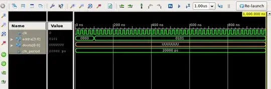
What gives?