5

I am using an IC (STM6600) which, among other functions that I need, is also capable of Undervoltage Monitoring. It works like this:

The IC monitors VCC in comparison to two thresholds, V_Low and V_High (which is just V_Low+V_Hysteresis).

  • When VCC < 3.10V (V_Low), then its status output = LOW (undervoltage condition)

  • When VCC > 3.30V (V_High), then its status output = HIGH (normal condition)

  • (Thus V_Hysteresis = 0.20V.)

The problem is:

  • I'd like the status LOW condition at VCC < 3.45 V
  • I'd like the status HIGH condition at VCC > 3.55 V
  • (Thus, I'd like V_Hysteresis = 0.10V.)

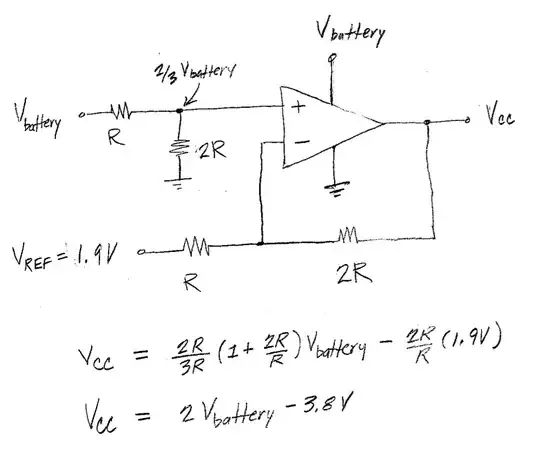
Since I obviously can't change the IC's operation itself, I am therefore trying to instead find a way to add some voltage-scaling circuitry in between my original supply (V_battery) and VCC of this IC. What are some ways I can accomplish this?

Note: I considered a resistive divider as well as a diode-based drop, but I couldn't solve it with either of those because the necessity above is not a proportional scaling. One other way might be to use a low-power microcontroller w/ ADC in between, read the voltage, and PWM-output the mapped/scaled voltage. But I was wondering if there are simpler options.

Thomas E
  • 715
  • 6
  • 16

2 Answers2

5

What are some ways I can accomplish this?

Using an offset and a gain, \$V + A(V_{battery}) = V_{CC} \$, the equations are:

\$V + A(3.45V) = 3.1V \$

\$V + A(3.55V) = 3.3V \$

The solution is:

\$ A = 2, V = -3.8V \$

This would be straightforward to implement with a simple opamp circuit. I can post one later if you're interested.


Also, really, I'm just interested in the academic value of knowing how to do this kind of linear voltage transformation generally speaking

Here's a circuit fragment to illustrate the basic idea. This should get you started.

enter image description here

Alfred Centauri
  • 26,502
  • 1
  • 25
  • 63
  • 1
    Yes, thank you, I would be interested to see especially how the offset part of the linear equation can be accomplished. – Thomas E Oct 11 '12 at 16:44
  • @ThomasE, what are the supply voltages available in your circuit? – Alfred Centauri Oct 11 '12 at 19:04
  • The supply voltage is the Li-ion battery supply. First, during discharge, the battery voltage begins at 4.10V and discharges down to 3.45V (at which, proportionally, I'd like the undervoltage point of 3.10V to be tripped on the STM6600). Likewise, during charge, the battery voltage begins from < 3.45V and rises, along the way passing 3.55V (at which, proportionally, I'd like the hysteresis point of 3.30V to be tripped on the STM6600). So I'd basically like the linear scaling stated in your Answer: Battery 3.45V "recorded" as STM6600 3.10V, and Battery 3.55V "recorded" as STM6600 3.30V. – Thomas E Oct 12 '12 at 07:21
  • Also, really, I'm just interested in the academic value of knowing how to do this kind of linear voltage transformation generally speaking, and then I can in turn adapt it to my exact circuit. – Thomas E Oct 12 '12 at 07:34
  • @ThomasE, I've added a circuit drawing to illustrate the basic idea. – Alfred Centauri Oct 12 '12 at 13:07
1

It's not clear, but are you trying to modify the STM6600 operation to get the scaled voltages or are you looking at doing something in parallel?

It is unlikely that you'll change the chip, because it is very likely that that chip has a on board bandgap reference so the detection points are fixed with some very clever circuitry and are even temp. stable. I know this because it says that it is also a voltage reference, I would use that Vref, some external low current precision OP-Amps and design the detection circuit that you want using precision resistors.

placeholder
  • 29,982
  • 10
  • 63
  • 110
  • Updated the question. I am trying to do something to the original supply voltage from my battery (which is input to CC of this IC) so as to scale/map it to the desired range. Does that clarify? I am NOT trying to modify the STM6600 itself. – Thomas E Oct 11 '12 at 16:19