8

How can I detect AC 'reverse polarity' (single phase) (without the use of ground/earth) and drive a led when the polarity is reversed?

It should at least detect 230 VAC but it would be cool/informative for future readers if the solution could work in US and EU (approximately 120 VAC to 250 VAC).

I did find this (non-isolated!) circuit, but I can not get it to simulate (the simulator complains that it needs ground or the LED blinks on both halves of the wave).
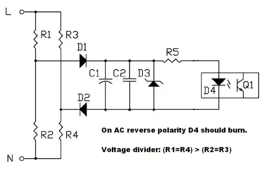
ac polarity detection ?
Source: 1 & 2

My questions are then:

  • Is the above schematic really functional and how does it work?
  • Is there a better or alternative way (MCU or perhaps even an IC) that does this?

Update:
Most current answers are leading me to believe one needs a reference. Now I'm thinking, why not create one? Something like a 'virtual ground' or somewhere along that line?

Update 2:
Today I read that older single-phase watt/hour-meters will run backwards if neutral and hot are reversed.. Why is this and couldn't the reason for this behavior be used in a 'equivalent circuit' that detects 'reverse polarity'?
Also, I wonder: could a hall-effect sensor be used to recognize a unloaded 'hot' wire, since a hot wire clearly emits a diversity of electromagnetic fields and elf radiation?

zduk
  • 203
  • 1
  • 2
  • 8
  • 1
    Are you trying to tell the wires apart, or are you trying to identify the half of the cycle when a particular one is at a positive potential relative to the other? – Chris Stratton Oct 11 '12 at 03:22
  • I want reversed polarity/phase indicator for single phase vac, using just hot and neutral, no ground and no tranny. I searched high and low for over a week, and the simulation indicates I'm on to something other than the known '3-led' circuit that uses ground that is of no use to me. – zduk Oct 11 '12 at 03:51
  • 1
    Again, are you trying to tell the wires apart, or are you trying to identify the half of the cycle when a particular one is at a positive potential relative to the other? – Chris Stratton Oct 11 '12 at 03:53
  • @Chris Stratton: I'm really sorry, thought the question was clear. I'm trying to tell the 2 ac-wires apart. Put differently, I want to know what conductor has 'neutral' and what connector has 'hot'. Put differently, I want a indicator if the mains wall is wired wrong (as in country's that have a wall-outlet that has different sizes of ac-power-plugs) or if I should plug-in the power-connector the other way round (for country's where one can plug in the connector both-way's). Does this help? – zduk Oct 11 '12 at 04:07
  • I may be simple but I don't see how you can identify neutral and hot without a reference ground so you can see which is closer/further away, or why the 'known 3-LED circuit' is of no use to you. – user207421 Oct 11 '12 at 08:12
  • @EJP: The 'known 3-led circuit' depends on ground for it's reverse-polarity detection thus it is of no use if no ground is available. Hence the 'academic' question how to detect ac polarity reversal (aka which conductor is hot/neutral) using just neutral and hot is a very interesting one. – zduk Oct 11 '12 at 09:20

9 Answers9

7

As other posters have suggested, this can't be done via conductive measurement alone. However, non-contact AC testers will properly differentiate line from neutral without a reference ground via capacitive sensing. This type of hand-held tester often has a flat plastic blade at the tip. Inserting the blade in the line slot will cause the LED to glow; inserting in neutral or ground will not glow:

enter image description here

There are a number of kits for this type of circuit, as we as many sample schematics available in a few minutes of searching (Search string: non-contact ac voltage detector circuit). They're essentially just high gain amplifiers that drive an LED.

Using this type of sensor permanently mounted near the Neutral line can serve as an indicator that your plug has been inserted the wrong way, provided that you have a reliable way (i.e. not battery) of powering the circuit.

HikeOnPast
  • 7,306
  • 2
  • 25
  • 20
  • I saw schematics of this thing, but it's not what I need, thank you none the less! – zduk Oct 11 '12 at 03:54
  • 5
    @zduk you have yet to specify what you need. – Chris Stratton Oct 11 '12 at 03:57
  • 3
    @zduk, your question was "How can I detect AC polarity (single phase) (without the use of ground/earth) and drive a led when the polarity is reversed?" This solves that problem. If you need something else, you need to clarify your question. – HikeOnPast Oct 11 '12 at 04:00
  • I can not build this into a psu/pdu. The front/back of the device should have a simple led/neon that indicates ac polarity reversal. If however this site is intended to enquire about electronic gadgeds instead of electronic schematics, then please point me to the correct forum/stack-thingy and accept my apology's for asking this in the wrong place. – zduk Oct 11 '12 at 04:14
  • 1
    @DeanB technically it does use ground (you holding it). :P – geometrikal Oct 11 '12 at 06:31
  • @zduk: "I can not build this into a psu/pdu" Why not? geometrikal makes a good point regarding the inherent reference ground provided by holding the device, but I suspect that the body of a PDU could be used in the same way, even if not explicitly grounded. What specifically do you believe prevents this type of device from being adapted to your application? – HikeOnPast Oct 11 '12 at 17:50
  • I just 'tested' this pdu-body idea with the neon screwdriver (see also Optionparty's answer) and a metal plate (isolated from myself). It SEEMS to me that the effect is LESS than with ME as a non-touch ground thingy. I have not fully discarded your idea yet, but the main things that put me off (apart from what I just mentioned) are: (1) in the image you posted one can see the detector lighting up on a regular cable (leading me to think I need quite some physical distance between neutral and hot, (2) especially inside a pdu there are going to be quite a lot hot and magnetic fields (relays). – zduk Oct 11 '12 at 20:44
  • Could someone test if this contact-less detector (as displayed in this answer's picture) works correctly without it laying on the ground or a human touching it? – zduk Oct 13 '12 at 15:15
  • I just found [this document from fluke explaining some more on capacitive coupled ('contact-less') indicators](http://electricalsafety.lbl.gov/assets/docs/proximity%20tester.pdf) that I thought I'd share. Since they say they might not work if the person holding them stands on a wooden ladder, I'm also curious if the work on a regular (cheap-ass) wooden stage.. More food for thought! – zduk Oct 23 '12 at 08:07
6

Just to try and clarify what some other people are trying to say: there is honestly no way to find out which conductor is "hot", and which conductor is "neutral" without a ground reference. Indeed, the terms "hot" and "neutral" have no meaning with out some sort of external reference - all "hot" means is that there is a large AC voltage between this conductor and the reference. Remember, voltage is always relative, and so with only two conductors coming in to a circuit we can only measure the voltage between them ("absolute" voltage simply doesn't exist).

Even the pen tester shown in another answer uses a reference - your hand. The object used as a reference doesn't necessarily have to conduct well, though it does work better. Usually the reason you need to know which conductor is "hot" is so that you can avoid a user touching it - where there can be a dangerous voltage difference, as the user is usually grounded (note that even here, we need a ground reference).

With this in mind, if you could provide some more details as to your situation, why you need to know which conductor is "hot", and why you can't use a ground pin, I'm sure we can be of more help :)

Side note: If the reason is simply that you are modifying existing equipment that does not have a ground conductor, but now need it (or something), is there any chance of just supplying an alligator clip that you can attach to something metal and grounded nearby, then use that as your reference?

skyrift
  • 196
  • 3
  • Sorry for the late response: I was contemplating, understanding and researching ideas and questions around my 'problem' that I distilled to this core-question. I want my pdu (glorified powerstrip) to detect and indicate (possibly even automatically correct using dpdt relay) "reverse 'mains' polarity" without relying on a 'protective earth' wire supplied by the 'wall-outlet' (since this is often not available or 'bootlegged' or the extra +/- 10ma from a led between hot and ground on top of existing acceptable small ground leaks might unnecessarily trip the ground fault circuit interrupter). – zduk Oct 24 '12 at 19:34
  • My main 'target' are live musicians (especially electric (bass-)guitars) on-stage in venues and bars. I want to eliminate the need for 1 (or 2 separate) 'wall-outlet checkers' that are usually needed (but virtually never used mainly due to the lack of time/space/light whilst setting up your gear (after a previous band has finished) and a clearly wide-spread mis-conception (or lack of understanding) regarding reverse polarity) prior to plugging in your 'main' powerstrip's powerplug (on which you have marked your polarity using permanent ink or something) into the 'wall-outlet'. – zduk Oct 24 '12 at 19:48
  • I understand this would also greatly benefit electrical inspectors (who also struggle with this problem), but also caravan and boat owners (reducing/eliminating 'hot dock', 'electric shock drowning' and corrosion problems). Essentially one could summarize this to: everyone that needs to plug their main power-supply into unknown receptacles on a regular basis. Think about it this way: one can (should) have everything connected to his 'power-strip' correctly polarized and wired; the one and only 'problem' is the 'jungle' of 'wall-outlets'. – zduk Oct 24 '12 at 20:00
4

You cannot do this without earth / ground.

AC is alternating current - the polarity between L and N flips 100/120 times a second.

geometrikal
  • 4,921
  • 2
  • 23
  • 41
  • I'm not ignoring your answer :) But for now I'm not ready to accept that it can not be done. Mankind has buggy's on mars.. then this should be possible to. By the way, the circuit I found and posted is the detecting-circuit in at least 2 patents (US20080024138 & US7446539) that disconnect the ac with a relay (and drive a buzzer) if the ac inlet is reversed. If you turn out to be right (that it can not be done), then those patents seem 'bogus' (I realise not all 'patents' work). – zduk Oct 11 '12 at 08:29
  • @zduk Both those patents are the same. The argument that something should be possible because there are buggies on mars doesn't follow. e.g. Mankind has buggies on mars therefore chickens should be able to lay sausages. :) – geometrikal Oct 12 '12 at 20:20
  • the 'apparatus' described in them and the patent-holder are the same. But the date (and I think the geological area they are valid for) seem to differ. _But more interestingly_: what do you think of that 'apparatus' (from which I took the detector-part). Are you 'shure' that device would not work or could I have misread it's use (and basic theory of operation)? Hehe, I understand your point of the sausage laying chickens but.. who would have thought 100 years ago we'd understand and manipulate gravity (google levitating frog). The 'mars-argument' was referring to technology, not 'magic'. – zduk Oct 12 '12 at 20:55
  • @zduk Pretty sure it wont work. Your simulation said it doesn't work either. The problem is AC by definition doesn't have a (fixed) polarity, only DC signals have defined polarity. If I showed you a picture of an AC signal, and another of that signal reversed, could you tell the difference? If not, then how would the circuit? Anyway this may all be a moot point, why not just add ground to your design? – geometrikal Oct 12 '12 at 20:55
  • p.s. levitating frog is not done by manipulating gravity, but cool video! – geometrikal Oct 12 '12 at 20:57
  • haha, you get my point. Things are 'magic' until understood. "why not just add ground to your design": since I cannot ad a properly grounded wall-outlet into my design, that would be indeed 'magic' haha. The contact-less detector sometimes also works with a antenna (I read). If one could sufficiently isolate/controll it's detecting-range it might work I'm starting to think. Furthermore if neutral is alway's about 0 volt and hot swings from positive to negative volts and current flows from high voltage to lower voltage, why couldn't one detect that? I'm still not convinced this is impossible. – zduk Oct 12 '12 at 21:03
  • @zduk Voltages are potential differences; they are given in reference to another point. e.g. measure a battery one way it gives 1.5V the other way it gives -1.5V. Neutral is tied to ground, so what you are really trying to do when you try to detect line or neutral, is detect which line is tied to ground. This is why everyone says you need ground, either directly, or indirectly (body, antenna,etc). So neutral is OV *with respect to ground*. Line oscillates +ve and -ve with respect to neutral, ground. Neutral oscillates +ve and -ve with respect to line. Take away ground you can't tell them apart – geometrikal Oct 12 '12 at 21:19
  • @zduk To elaborate, imagine neutral was at 0V (w.r.t ground) and hot was at 60V. Current would flow from hot to neutral. Now half a cycle later, neutral is at 0V w.r.t ground, hot is at -60V. Current would flow from neutral to hot. Now take away the ground reference. In the first case hot is at 60V w.r.t. neutral, in the second case, neutral is at 60V w.r.t hot. Half a cycle later hot is 60V wrt to neutral, half a cycle later neutral is 60V wrt hot. Wait up ... which half-cycle am I up to? – geometrikal Oct 12 '12 at 21:26
  • Ok, so within the circuit connected to the 'loop' one cannot detect it that way. But what about a neutral and hot that do not have any current flowing (no load) between them? If I understand correctly: a contact-less detector (working with a antenna) will not light up on null, but does light up on hot right? So let's say I tap 1 (unknown) ac wire connected to nothing and put such a detector there with a short range and sufficient 'shielding?', wouldn't that detect the polarity? IE: if the detector fire's, this is hot, if not, it's null? – zduk Oct 12 '12 at 22:02
  • Another idea: say one creates a steady voltage (possibly dc using a bridgerectifier). If you reference this reference voltage to null (outside of the dc-circuit), wouldn't this be reasonably steady, while if you reference it to hot (outside of the dc-circuit, the one that carries the sine-wave) the voltage-difference would fluctuate (in relation to the hot sinewave)? – zduk Oct 12 '12 at 22:39
  • 1st comment - contact-less detector works by creating capacitively coupled connection to ground. Should work, but you will need some kind of ground connection somehow. 2nd comment - what is this 'null' you are referencing to? Let's say you have wires A and B, one is neutral and one is hot but you don't know which one. You create a DC offset from A, lets call that C. Voltage between A and C is a fixed value that you created. Voltage between B and C is oscillating. But still, which is hot A or B? – geometrikal Oct 13 '12 at 01:22
  • Anything that plugs into an outlet with no ground, doesn't need to know which is hot and which is neutral. So what is the application? Why do you need this? – geometrikal Oct 13 '12 at 01:23
  • 1
    "Anything that plugs into an outlet with no ground, doesn't need to know which is hot and which is neutral." As far as I know/understand, people (especially musicians, even famous ones) DIE from this 'mis-conception'! This is not theory but reality. 'Officially' you always need to check wall-outlet polarity (especially when using vintage 'hot chassis' amps and such). Theoretically you're right (if everything is connected and wired to 'modern' rules/codes), however the 'real world' is a jungle. There are more applications, but I'm happy to just detect 'mains' polarity (50/60hz 100-250vac). – zduk Oct 13 '12 at 14:21
  • What about the contact-less circuits that use a antenna to detect the 50/60 hz oscillation? Like [this](http://www.redcircuits.com/Page35.htm)? Would that principle overcome the need for a capacitively coupled (third) ground-connection or the human body like [this](http://discovercircuits.com/DJ-Circuits/active-acline.htm)? About A/B wire reasoning: is the following equivalent to your explanation?: create DC voltage C from current _between_ A and B, then compare voltage C to either A OR B. If that one oscillates then should be hot? – zduk Oct 13 '12 at 15:12
  • Whoa I did not know about the hot chassis design. That is nuts. – geometrikal Oct 13 '12 at 21:33
  • 1st link - requires some kind of ground to detect hot instead of neutral, otherwise detects both. A/B wire - voltage C needs a reference to what wire, A or B? then same problem. What you are asking is "how do I measure AC polarity", but AC by itself, by definition has alternating polarity. So the real question is "how do I detect which line is hot", which is the same as "how do I detect which line is not connected to ground". But you then want this without using ground. Line and neutral are *defined* by ground, so you can't detect which is which without including ground. – geometrikal Oct 13 '12 at 21:43
  • Here is a proposal. Create a circuit like in your second link, but have the thumb electrode built into the plug. That way when the person plugs into the wall socket they will be touching the electrode and supplying the ground you need for detection. – geometrikal Oct 13 '12 at 21:47
4

I can't imagine the patented circuit being able to detect anything other than when N is at a higher potential than L, which happens 50-60 times per second depending on the frequency of the utility providing power.

The reason neutral can be discriminated from hot at all is that most of the time (in North America at least), a TN earthing system is used: the netural is bonded to protective earth somewhere in the scheme. Bearing this in mind, you can see how easy it is to detect neutral from hot when you have access to protetive earth - because of the bonding, you'll never measure a significant signal between neutral and earth, but you'll see the full AC waveform from hot to earth. This is why you cannot detect hot from neutral without a protective earth connection!

Adam Lawrence
  • 32,921
  • 3
  • 58
  • 110
  • Ok, so it looks like the patent is bogus and it's inventor a $%^& liar who wasted his (or his boss's) money on a non-functional patent. But why can't one detect that 'neutral' does not 'oscillate' (in voltage, not current) where-as 'hot' does? Or detect elf emissions of the hot-wire, just like a non-contact tester (that operate on at least 2 different way's). Or detect (and comb-filter) 50/60 hz (or it's third harmonic) like a radio. Or use capacitive coupling: if the capacitive coupled wire (parallel or wound around the hot conductor) starts to oscillate. Or what about hall-effect? – zduk Oct 29 '12 at 18:59
  • Anything is patentable these days - whether or not the idea 'works' is irrelevant. You've already stated that you can't use any of the non-intrusive methods, and it's been discussed already how those methods need some earth reference (even through a human body) to work. Endgame, methinks. – Adam Lawrence Oct 29 '12 at 19:19
  • I just did a test: insert a 1.5 meter 3 wire 'kettle-cable' (hot, neutral and ground) into a ungrounded receptacle, thus in this cable the ground-wire is not connected. When I insert my neon screwdriver into the ground-pole at the other end of the cable and touch it, the neon lights up (as I learned during my research on this topic). Maybe this effect can be used? Also, a battery-powered radio suspended in the air still works correctly. If a hot-line emits elf (which is low frequency radio-frequency's), then why can't I also detect a hot wire without a human as completing ground circuit? – zduk Oct 29 '12 at 20:06
  • I'd be happy (if this is the only way) to provide a touch-'pad' on the pdu that the user must touch so there is a ground path for detection, however it would then be useful to also use the same pad as the main power-on switch. Even with a simple neon and some light-detecting component this could work (as stated in other answers). But then.. what about the wooden stage.. what about (magnetic/elf) isolation of the detector (if one of the contact-less principles is used) and what would be the optimal detecting method: u shaped antenna or coil or a wire parallel? – zduk Oct 29 '12 at 20:06
1

enter image description here

Usually C1 is our body which has a large capacitance, but a simple piece of metal, a wire, a conductor with a large mass, will work as well.

The larger the mass, the larger the capacitance, the brighter neon lamp gets.

Normal large value caps wont work. This is electrostatic, only the mass of the conductor determines the capacitance.

I was able to slightly light up a NE-2 type neon lamp with just a 60cm wire attached as C1.

Update: After giving it a second thought I realized is not the mass that counts, it's the surface area that matters. You are effectively forming one plate of the capacitor while the other plate is the ground.
But principle is the same, you need a large conductor hanging loose to capacitively couple the AC voltage to ground.

Chris
  • 554
  • 6
  • 13
1

The question of AC "polarity" is really just a special case of the question of AC phasing, and it can only be answered with respect to a second, "reference" AC signal. The first signal can be in phase or out of phase with the second one, or indeed, have any other phase relationship to it.

Your two-terminal circuit cannot determine polarity or phasing in any sort of absolute sense. Its behavior will be identical for any AC signal you feed into it.

Having reference to a separate "earth" ground will only tell you which of the two lines is "neutral" (i.e., the line bonded to ground at the service entrance). This is what the typical 3-light outlet tester will tell you. But even this device can't tell you which phase of the power line you're on.

Dave Tweed
  • 168,369
  • 17
  • 228
  • 393
  • also @geometrikal: I did a quick simulation of the divider-part. See this image: http://i45.tinypic.com/25u4aih.gif If what you guy's are saying is true (ie a hot and neutral wire is not enough), then why does this work in simulation? If this simulation works as in real life, then why (if desperate) couldn't I use a mcu/comperator to compare the 2 voltages? – zduk Oct 11 '12 at 03:43
  • Which node in the circuit is the reference from which these voltages are measured? It must be the left side of the AC source, and so you have an implicit third connection that you're taking advantage of. Right now, this circuit is simply telling you which of the two switched lines is connected to that node. Is that all you're after? – Dave Tweed Oct 11 '12 at 03:53
  • Sadly I have no clue where simulator "crocodile clips" places its 0-volt reference node (and cannot find an answer). I'm trying to tell the 2 ac-wires apart. Put differently, I want to know what conductor has 'neutral' and what connector has 'hot'. Put differently, I want a indicator if the mains wall is wired wrong (as in country's that have a wall-outlet that has different sizes of ac-power-plugs) or if I should plug-in the power-connector the other way round (for country's where one can plug in the connector both-way's). Does this help? – zduk Oct 11 '12 at 04:22
  • @zduk I understand what you are trying to do, but it cannot be done with just line and neutral. Consider the sine wave form of the signal - move half a cycle and polarity is reversed. In any case, if just line and neutral are coming into the PSU, with no earth, then it doesn't matter which way around it is. If it mattered then the plugs wouldn't be the way they are where you can put them in either way. – geometrikal Oct 11 '12 at 06:30
  • @ DaveTweed: your second comment was a good nudge on the simulator-part. However I still don't know if the measurement references the 0-volt or ground-point. How could I test this? I managed to get different readings using a simulated volt-meter. I referenced the voltmeter after the dpdt switch to the line that should be connected to 'neutral' when ac is not connected in reverse. @geometrikal: let's stay with the distilled question and leave out possible use ('deathswitch', 19-inch rack, ungrounded wall-outlets, dodgy bars, or for all I care just a fancy lcd info item) for now :) – zduk Oct 11 '12 at 08:51
  • I re-read your answer quite often and I did a lot more reading on 'polarity' versus 'phase' (including a lot of different governmental regulations). Both terminology's appear to be correct but thy refer to 2 different things: polarity being L* vs 'neutral' and phase being L1 vs L2 (for example). I learned that 2 musicians on a different phase singing in the same microphone COULD get shocked to. I understand there is no way to detect from just L* and 'neutral' what phase L* is (ie L1, L2 or L3). Detecting phase(difference) is most definitely intriguing, but for this question I'm after polarity. – zduk Oct 24 '12 at 20:32
0

A neon bulb will glow lightly when connected to >90acv.
So the Hot line can be identified.
It should be possible to design a ciruit to detect the light.

Optionparty
  • 636
  • 1
  • 5
  • 9
  • Is this without (you as) a ground? How the neon glow lightly with just a vac line connected? Maybe this could become a viable solution? – zduk Oct 11 '12 at 07:57
  • Yes, just one wire connected. This is a way electricians identify the live wire in old buildings without color coded wires (nob & tube wiring). The high voltage/frequency inside a crt tv will light the neon bulb without any wires connected. Neon bulbs have other interesting properties. Some plastic screw drivers have a bulb in the handle, with one connection. – Optionparty Oct 11 '12 at 08:48
  • Actually, I have one of those. It has a metal tip on the back of the screw-driver and I know that if I put my finger on this metal back the light burns more brightly. Thus indeed I was aware that the light also glowed a little without me touching the metal back (I forgot I alway's wondered why). Anyhow, I immediately tested it together with geometrikal's explanation on how the contactless ac-tester worked: the further I moved my hand away from the screwdriver (centimeters) the less the bulb glowed, and after about 6 cm it was completely dark. So.. am I missing something here? – zduk Oct 11 '12 at 09:07
  • http://en.wikipedia.org/wiki/Test_light – Optionparty Oct 11 '12 at 09:13
  • I also use an "Outlet" tester as in the last picture. I have an outlet "Ground Fault" for use in Europe, as I will not trust my life to an unknown electrician or his helper. After I id the hot wire, I cutoff about a foot of local extention cord, put on my own plug on the other end, paint the cord polarity, and plug in the "Ground Fault". – Optionparty Oct 11 '12 at 09:22
0

Not a complete answer, but maybe it will be enough for your case:

Integrate the detector from DeanB's answer into the plug and send the voltage from the detector's LED to a microcontroller in the PSU. When the system starts up, the microcontroller should detect whether there is a voltage coming from the detector LED and set a LED in the PSU accordingly. Whoever inserts that plug in the outlet will be obviously holding it in hand, hence the detector will function at that moment. When people release the plug, the microcontroller will see a change in the voltage coming from the detector, but it should ignore it and keep the PSU LED as set before.

This will work anytime someone plugs the device into a powered outlet, but it WILL break in the following cases:

  • When polarities can be swapped at the mains, without someone pulling the plug out and in again. The microcontroller has no chance of detecting this since there's nobody to hold the plug.

  • When someone turns the mains switch off, changes the plug's orientation, and turns the mains on again. Same as before.

I don't know whether the live and neutral lines differ in any other characteristic you could measure. I am guessing -- and I may be completely wrong -- that, since the live wire has no contact with earth anywhere, it should be an excellent antenna. The neutral on the other hand does have such a contact relatively near, so it should be not as good an antenna. Maybe you can detect this?

Erion
  • 385
  • 1
  • 5
  • Your first idea (deanb's contactless detector + geometrical's ground explanation fitted inside the plug) is a nice idea (+kudos for detailed explanation). However, it probably needs some power-supply to (or the power-cable would need another (2?) strands extra). Fitting all this inside a power-plug seems tricky to and limits the options of buying/borrowing a replacement power-cable. The antenna-idea however sounds very intriguing; maybe someone will have an 'aha-moment' with this idea (although I THINK this would not work when connected to a dc-ac inverter or online ups). – zduk Oct 11 '12 at 07:55
-1

For live/neutral detection, you must have an earth/ground connection as the basis of measurement. You can use other connections with high electrical resistance, but it requires a complex electronic circuit. Of course this device is available. Search for "Alborz Ertebat" or "LNC-DSP1" in Google and Youtube.

winny
  • 13,064
  • 6
  • 46
  • 63
  • Your answer could be improved with additional supporting information. Please [edit] to add further details, such as citations or documentation, so that others can confirm that your answer is correct. You can find more information on how to write good answers [in the help center](/help/how-to-answer). – Community Jan 24 '23 at 14:52