1

EDIT: My reference in this question to analogue voltages are just how my voltmeter reads and averages the PWM from the Microbit. Apologies if I'm confusing the matter with this. The project is using PWM with a varying duty cycle.

I'm trying to power a strip of 12v 5050 LED's using the circuit below. I'm changing the output of the Micro:bit between 0 and 1023 in steps of 128 to get 9 levels. At the MOSFET gate I'm getting between 0 and 3.14V in steps of 0.4V and without a load I'm getting between 0 and 12.16V at the drain in steps of 1.5V (the first step is 2V and the last step 0.95V but I assume the response just isn't quite linear). When I connect the LED strip the drain voltage drops to about 40% of what I am expecting i.e. 0 to 4.75V which makes the LED's barely visible. Can someone explain why this is please? The power supply is rated at 12v 3A so has plenty of capacity. The LED's shine at full brightness when connected directly to the power supply.

My electronics knowledge is very basic - some 30+ year old school physics and a lot of Googling so feel free to respond using "for dummies" level answers.

schematic

simulate this circuit – Schematic created using CircuitLab

Jim Hudd
  • 55
  • 4
  • The key mistake here is that these are not, and should not be, varying voltages. They're varying duty cycle of *full voltage* at each stage. It's unclear how you are measuring a voltage on the load without the LED strip, as the LED strip is the load and the only way to source current to the drain. Ideally, in the "on" part of the duty cycle you should measure almost no voltage drop across the FET, and all of it across the LED strip. With a voltmeter you can only debug the 100% duty cycle case, you need a scope to look at the lower duty cycles, but get 100% duty working first. – Chris Stratton Apr 18 '19 at 14:13
  • Based on the explanations I've read of how PWM works with 5050 strips, you appear to get an analogue voltage out of the microbit when read with a voltmeter. This is because the voltage switching on an off averages out based on the duty cycle. In my case the duty cycle is varying between 0 and 100% using the 0-1023 values. The PWM period is set to 20ms which seems to be the default for the Micro:bit. I've tried increasing and decreasing the period but it hasn't affected the brightness. It did make the LED flicker at one point - I don't recall if that was at a higher or lower period. – Jim Hudd Apr 18 '19 at 14:26
  • I'm measuring the voltage by taking the LED strip out completely and putting the positive probe on +12V and the negative probe on the drain. I guess the voltmeter itself is the load in this case. – Jim Hudd Apr 18 '19 at 14:28
  • Changing the PWM frequency or overall period won't change the brightness until you run into limitations of the technology or perception. What works is changing the *duty cycle* as you already have been. You are already using PWM, you just need to make sure the circuit is working properly at 100% duty and the rest should follow. Your FET seems like it should work with 3v3 gate drive... – Chris Stratton Apr 18 '19 at 14:39
  • It may be useful to increase the period significantly (to 1000 ms) just so you can visually debug what is happening. Most multimeters will not give a useful reading on PWM - you'd really want an oscilloscope at that point. – W5VO Apr 18 '19 at 14:43
  • Setting a 1s period I can see the LED's turning on an off based on the duty cycle so that part seems to be working fine but the LED is just so dim as to be barely visible. I've tried 6 different MOSFET's and all exhibit the same behaviour so I don't think I have a faulty MOSFET unless I'm really unlucky. – Jim Hudd Apr 18 '19 at 14:51
  • Try putting 3v3 directly on the gate, and use your meter to figure out where the voltage drop is. It should be across the LEDs, if it is across the FET it is damaged, miswired or mischosen, though the part number you list should work if correctly applied. – Chris Stratton Apr 18 '19 at 15:11
  • I tried a couple of AA batteries directly on the gate and got the same result - barely visible LED's but three AA batteries turned them on as expected. So despite the kit I bought supposedly working directly with Micro:bit's (and Arduino's) it looks like it doesn't. I either need to use a different MOSFET that responds to a lower gate voltage or boost the voltage being fed to the gate somehow. – Jim Hudd Apr 18 '19 at 19:23

2 Answers2

1

You're trying to control the current through an LED strip by using an NMOS transistor. This solution can work (somewhat) but has several issues:

  • It is difficult to control the current, the NMOS is designed to respond "abruptly" to a change in \$V_{gs}\$. This is because these NMOS are designed for switching applications, meaning on or off. What you need is something between on and off, more like a resistance.

  • In the "resistance" mode you need, it is very difficult to keep a constant resistance. The resistance is very dependent on temperature. When used as a resistor the NMOS will heat up changing its resistance, which is what you're trying to keep constant!

  • For light loads this scheme will be OK, the NMOS will not warm up too much. But when the current increases more heat will be dissipated and keeping the NMOS cool can become an issue.

Fortunately there is a solution which solves most of the issues: PWM (Pulse Width Modulation). With PWM we switch the NMOS transistor on and off so quickly that human eyes cannot notice it. A PWM frequency above 200 Hz is often sufficient.

Due to the fact that the NMOS is either fully on or fully off, it will not dissipate much power so a high current through the LEDs is no issue.

Also dimming can be smooth as a 1 % PWM signal switches the LEDs on for 1 % of the time and off for 99% so you really get 1% of the full brightness.

As the Microbit contains a micro controller, it should be able to generate such a PWM signal and quite accurately as well.

You can re-use the schematic you already have. I am too unfamiliar with the Microbit to tell you if you can use the same output you're using now but chances are that you can. You might just have to set it to "PWM" instead of "analog" or "DAC mode".

Bimpelrekkie
  • 80,139
  • 2
  • 93
  • 183
  • Actually, this isn't a current control project - it *already is* a PWM control project (all the source MCU board can do), the asker is just not fully aware of that and its implications, in part because their only test instrument is a voltmeter which they see sort of averaging the PWM duty to a voltage, and perhaps because they may be using a software API that passes off PWM duty as if it were an analog level output. – Chris Stratton Apr 18 '19 at 14:35
  • The Micro:bit doesn't actually have any analogue output and uses PWM to simluate this. Setting an output value using wrte_analog(1023) sets the PWM duty cycle to 100%; write_analog(511) sets it to 50%. When measured with a voltmeter these appear as 3.3V and 1.65V respectively (or close anyway!). Driving 5V LED strips directly from the Micro:bit works but I want to use 12V strips as they're brighter. Based on your reply above it looks like I'm doing the right thing already. There's some info on the PWM here https://microbit-micropython.readthedocs.io/en/latest/pin.html – Jim Hudd Apr 18 '19 at 14:38
-1

FET's are non-linear Voltage controlled resistors except the threshold has a wide tolerance. This means there is a big tolerance for just the threshold voltage which is not enough to be used as a current switch. You need at least 2x to 3x the threshold voltage to conduct high currents where the guaranteeon yours is only at Vgs=5V and not 3V.

You made a good choice of FETs for RdsOn but not a good method of gate control.

This is why they are non-linear.

Gate to Threshold Voltage Vgs(TH) = 1 - 2 V when Vgs = Vds , @ Id = 250µA, Figure 10

Drain to Source On Resistance (Note 2) rDS(ON)=0.047 Ω I D = 30A, Vgs = 5V, Figure 9 - -

The drain-source resistance is very high (60V/25uA) at Vgs=0, then the Vgs(th)=Vt threshold may occur anywhere from 1 to 2V to ~6 kΩ avg = 1.5V/250uA since 1V/250µA = 4kΩ and 2V/250µA=8kΩ

The 2nd important parameter is RdsOn=0.047Ω @ Vgs=5V which is ~ 3x the gate threshold voltage, , Vt (aka) Vgs(th). So in between 5V and Vt (= 1 ~ 2V) it drops from 6k to 50m or nearly 5 decades. So very non-linear current vs gate voltage. AND you need at least 2*Vt to switch decent current, and 3* for lower losses.

I have superimposed some Vgs to Vt ratios on the datasheet curve to show these more clearly vs Drain current.

![enter image description here

Suggestions

To use a power FET as a dimmer there are 2 simple options;

  • PWM with Vgs >= 3V fixed frequency , variable duty cycle from a uC
  • Voltage control Current sink using a comparator with say 100mV max drop across R from Source to Gnd and control from 0 to 100mV into comparator to drive gate from a fixed voltage and pot divider or DAC output.

p.s. The blue text is a rule of thumb and the tolerance for Vt =1.5V avg +/-0.5V but as the Vgs increases the current follows these curves at 25% C and stated Vds and the guaranteed value for RdsOn is in the table at 5V.

Yet in-between it is non-linear.

a simpler choice of FET has a threshold Vt<= 1V instead of 1 to 2V which has a RdsOn <= 0.1 Ohm.

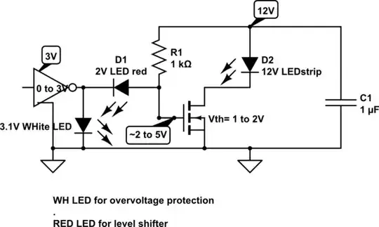
But to make raise Vgs, you can also do this.

schematic

simulate this circuit – Schematic created using CircuitLab

Another solution for your 1 to 2V Vgs(th) from 3V

schematic

simulate this circuit

As I wasn't expecting your drive to be so low V, there are logic level FETS suitable for this task as well. Ensure current rating is 2x what you need to keep cool.

  • ZXMN6A08GTA Diodes Incorporated MOSFET N-CH 60V 3.8A SOT223
  • STN4NF03L STMicroelectronics MOSFET N-CH 30V 6.5A SOT223
  • IRLR2703TRPBF Infineon Technologies MOSFET N-CH 30V 23A DPAK
  • IRL2703PBF Infineon Technologies MOSFET N-CH 30V 24A TO-220AB
Tony Stewart EE75
  • 1
  • 3
  • 54
  • 182
  • I'm don't fully understand this I have to be honest (sorry!) but based on your first simple option it looks like the Microbit just isn't outputting a high enough voltage? At 100% duty cycle the output is 3.14 V but perhaps that isn't quite enough. Do I need to chain a couple of the MOSFET's to increase the voltage to the one the LED strip is connected to? I chose these MOSFET's because they are supposed to work directly with micro controllers so I'm a little wary of chaining them unless people much cleverer than I suggest it. – Jim Hudd Apr 18 '19 at 15:13
  • A common emitter NPN with pullup gate resistor to 12V can amplify your 0 to 3V to get 12Vgs=12V which is more than enough. but a simpler choice of FET has a threshold Vt<= 1V instead of 1 to 2V – Tony Stewart EE75 Apr 18 '19 at 15:15
  • Do you know of a FET with a threshold <= 1V? The only ones I can find at 1-2V (the ones I have) or 2-4V. To be honest shouldn't a threshold of 1-2V still work when the Micro:bit is providing 3V anyway? From my test detailed above I got the same dim LED's by using two AA batteries on the gate but three AA's lit the LED's properly, so despite the datasheet listing the threshold as 1-2V it's seems to be somewhere above 3V and <= 4.5V. – Jim Hudd Apr 18 '19 at 19:38
  • You are confusing the Vgs and Vt= threshold for weak current also called Vgs(th) Vt=Vgs(th)=Vds= 250uA) so read my graph. .... Vgs needs to be at least 2 to 3x Vgs(th) or 4V to 5V – Tony Stewart EE75 Apr 18 '19 at 19:51
  • ignore the village idiot -1 – Tony Stewart EE75 Apr 18 '19 at 20:23
  • So a bunch of IRL2703PBF's arrived this morning to replace the RFP30N06LE's and everything is working exactly as I expected. Thanks to everyone for their help with this. – Jim Hudd Apr 24 '19 at 13:51
  • Yes thanks to everyone who voted on this that helped me. – Tony Stewart EE75 Apr 24 '19 at 14:04