I need to convert the external control voltages of +4/-4V range to 0/5V in order to replace now obsolete SSM2050 with micro controller based solution inside an old vintage synth. Is there any easy and lightweight solution (like voltage divider) to accomplish this task?
Asked
Active
Viewed 423 times
0
-
Convert for what? Is it a signal or a supply? Who will "consume" it? – Eugene Sh. Apr 08 '19 at 17:01
-
+/-4V - control voltages of ADSR Generator that I want to replace with micro controller based solution – Roman Apr 08 '19 at 17:02
-
Thank you for editing your question. Have you also looked into some DC-DC conversions? i.e. something like a [charge pump](https://en.wikipedia.org/wiki/Charge_pump) – Apr 08 '19 at 17:14
-
1Take a look at this https://electronics.stackexchange.com/questions/265440/scaling-and-adding-to-voltage/265474#265474 And to get 0V at the output for -4V at the input and +5V at the output for +4V you need +10V and Rp = 25k, Rg = 50k, Ri = 10k – G36 Apr 08 '19 at 17:31
-
G36 : this method works but it requires additional +10V source. – Roman Apr 09 '19 at 07:36
3 Answers
2
To use the 3 resistor method described in the above link you must have a voltage supply rail greater than +5V (for your I/O voltage specification).
Here is a design along the same lines but with a supply rail of +12V.
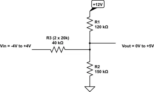
simulate this circuit – Schematic created using CircuitLab
To determine the resistor values I set up two equations, one using the voltage divider law with Vin = -4V, and a second equation using Millman's theorum with Vin = +4V. Assuming a value for R2 and a value for the supply voltage, there are then two simultaneous equations and two unknowns (R1 and R3) which means that both equations can be solved and the values determined for R1 and R3.
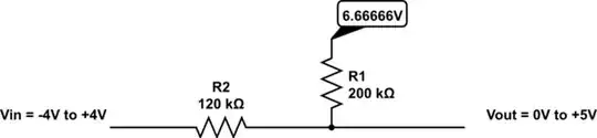
It is possible to design this sort of solution using only two resistors but it can only be achieved with one supply rail voltage value which is 6.66666V (for your I/O voltage spec.) so an adjustable voltage regulator would be needed such as the LM317T.
If you haven't got access to a supply rail above +5V then perhaps you could consider using my op amp solution above.
-
I'm not sure what the "official" etiquette is about this, but I've always assumed that multiple answers from the same person should generally be merged into one answer presenting multiple possible solutions. – Hearth Apr 10 '19 at 18:50
1
Here is a method that does not require any additional power supplies. The op-amp should be a rail-to-rail IO type that is happy operating from 5V only. There are many options (eg. MCP6021). The resistors are standard E96 series values. R5 can be a 5% type, its purpose is to bias the TL431.
The TL431 forms a stable and relatively low-noise 2.50V reference from the 5V bus.
simulate this circuit – Schematic created using CircuitLab
Spehro Pefhany
- 376,485
- 21
- 320
- 842
0
simulate this circuit – Schematic created using CircuitLab
-
If you find that the output accuracy is being affected by the 16k input resistance being too low for your output resistance then change the 16k to 160k and change the feedback resistance of the first amplifier to 100k, Also don't forget to add a 100nF decoupling cap across the op amp's supply pins. – Apr 09 '19 at 20:27
-
I should've said LM317L (TO92, 100mA version) rather than LM317T which would be overkill. – Apr 11 '19 at 14:09