4

I am currently working on a project that aims to provide 12v 10a in the final output.

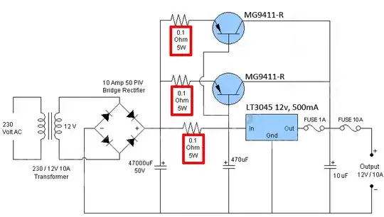
I am quite new to EE and wasn't quite sure if I have choose the correct resistors value as highlighted in the diagram below in red.

Could some of the experts here advise and explain so that I could learn and elaborate in the future, thanks alot!

Courtesy of www.circuitdiagram.org, and redrawn by me

Image courtesy of www.circuitdiagram.org, and redrawn by me

enter image description here

I have redrawn the schematic, hope it helps!

Patrick
  • 41
  • 3
  • You should read [this question and answer](https://electronics.stackexchange.com/questions/28251/rules-and-guidelines-for-drawing-good-schematics) on drawing schematics. Yours doesn't make it clear where lines are connected together as opposed to just crossing over. – Finbarr Apr 08 '19 at 16:42
  • 1
    Guide to schematics: Either (1) Crossing lines NEVER join. Joining lines never cross. Follow that and what you intend will always be clear. or (2) Put dots where crossing lines join. This may not survive photocopying or machine washing :-). – Russell McMahon Apr 08 '19 at 17:39

1 Answers1

1

I wouldn't normally do a 10A supply with a linear regulator unless there is some compelling reason, but it can be done effectively.

With the outboard boost circuit, the effective resistance to engage at 0.5A (which your regulator is rated for) would be 1.2 ohms but that would be too close to the regulator capability for my liking.

The circuit below is how you could do it (ignoring the input transformer and smoothing and output decoupling so we focus on the boost circuit):
schematic

simulate this circuit – Schematic created using CircuitLab

The transistors will engage at Iin ~ 0.6V / 2 = 300mA (well below the regulator capability).

The resistor should be rated for 0.5W (so there is a lot of headroom). The actual dissipation will be more like 180 mW or so (depends on Vbe to turn on the transistors which may be as high as 0.9V which is why I chose a current well under the regulator capability).

You only need a single resistor; note that when drawing schematics, clarity is key.
Peter Smith
  • 21,923
  • 1
  • 29
  • 64
  • 2
    I think the emitter resistors are there to make sure the multiple power transistors share current more evenly. – Dave Tweed Apr 08 '19 at 16:09
  • 1
    The emitter resistors are for current sharing. I might consider a fold-back using three BJTs and I'm not sure why the OP cares to use an LDO (PNP/PFET) as there are stability issues. Just a standard regulator might be fine. I also lament the missing bleeder resistor and a couple of other minor details such as inrush current limiting. – jonk Apr 08 '19 at 16:11
  • Thanks for the replies and comments. The resistors at transistors are included for stability and prevent current swamping as the manufacturing tolerances of dc current gain will be different for each transistor. Should I :- 1. Build three BJTs and with 3 nos of 0.1 ohm 5w resistors at emitter for sharing the power more effectively?; 2. 2 ohm 0.5 watts at the LDO's input?; Thanks again! – Patrick Apr 08 '19 at 16:38
  • The emitter resistors are needed to avoid thermal runaway. – analogsystemsrf Apr 08 '19 at 16:39