This is your circuit drawn as a schematic to read for understanding rather than as a wiring diagram (which is more about getting everything connected and not so much for understanding it.)

simulate this circuit – Schematic created using CircuitLab
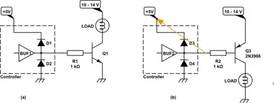
The idea illustrated in your diagram, where the LED and a current-limiting resistor are placed in series in the collector circuit, is a common (and reasonable) approach. The BJT is operating as a "semiconductor switch" and this is one of several approaches for that behavior. So far, so good.
But the idea of directly tying \$+5\:\text{V}\$ to the base, when the emitter is also nailed down to ground, is not common and it's not good. This directly places a full, forward-biased \$5\:\text{V}\$ across the base-emitter diode. Keep in mind:
- You only need from as little as \$600\:\text{mV}\$ to perhaps as much as \$900\:\text{mV}\$ (in most cases) to use the BJT as a switch.
- For each additional \$60\:\text{mV}\$ (typically) you will get 10 times as much collector current (if permitted by the circuit portions connected to the collector) and 10 times as much base current (always possible.) Broadly speaking, the base current will be exponentially related to the applied forward-biasing voltage across the base and emitter.
You were applying \$5\:\text{V}\$!! This is way, way, way above what you should have been using. So the BJT was being literally flooded with base current. Of course it was getting hot! It was dissipating serious power. Might have even damaged the device (I'd probably throw the part away, in fact, after doing something like that.)
This is why a resistor is often applied to the base circuit.
simulate this circuit
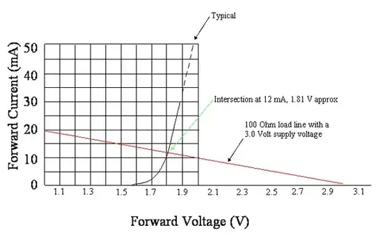
The base resistor's voltage drop is a simple linear relationship to the current passing through it. The BJT's base-emitter junction current is an exponential relationship. So as the BJT's base-emitter diode junction tries to rapidly increase it's current, the resistor in series with it opposes this rapid change by dropping voltage. Very quickly, it will turn out that the resistor drops enough voltage so that the base-emitter junction's voltage is close to where it should be.
By using a resistor, you permit the base voltage to "find a stable and reasonable voltage drop" for its operation.
As others have pointed out, the Maximum Ratings section also specifies an absolute worst case reverse-biased voltage for the base-emitter. This is because the base-emitter PN junction diode can't handle a lot of reverse-bias voltage in a typical BJT. Diodes used in bridge rectifiers can often handle very large reverse-bias voltages across them. But not so much with BJTs. They aren't designed to handle much of that kind of stress. Instead, they just break down and avalanche. So the ratings there tell you what to watch out for. Often, people will add a separate diode (oriented opposite to the forward direction of the base-emitter junction of the BJT) going from base to ground in a case like this to protect the BJT ... just in case.
