1

I have searched for troubleshooting the ULN and did not find any solution.

I use a ULN chip in a motor inverter for controlling precharge relay and main relay. The problem is when the motor inverter is powered off, and for instance the charging is on (battery charging) the relay will kick in getting negative trough the unpowered ULN??? Sounds strange, but It's happening. And I don't want the motor inverter ON all time (uses power and draining the battery)

I can not disconnect GND from inveter. I can not disconnect POS from relays.

Is there a "easy" solution to this??

enter image description here

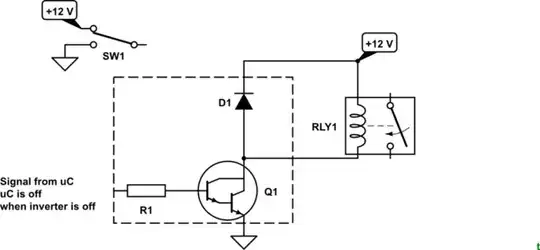
The relay is connected to +12V and one output pin on the ULN. The ralay gets some "creepage" current from the ULN, enough to energize the relay. Happens when inverter is off, but other devices are on (like charging)

schematic

simulate this circuit – Schematic created using CircuitLab

Johannes
  • 11
  • 2
  • 1
    There's no sign of a relay or the negative supply so it's going to be hard to help. – Transistor Mar 31 '19 at 09:16
  • Your edit hasn't helped much. You need to post the relevant parts of the schematic. Note that using a block symbol for the ULN2003 hides the internals for you making the *schema* much more difficult to understand. – Transistor Mar 31 '19 at 13:54
  • You forgot the lost important: what signal does the input of the ULN2003 have when the inverter is off? If it still high, the darlington inside the ULN2003 will still be turned on no matter whether the inverter is ON or OFF. – Huisman Mar 31 '19 at 16:48
  • Sorry, the uC is part of the inverter, same power source. – Johannes Mar 31 '19 at 17:59

2 Answers2

1

enter image description here

Figure 1. Internal diagram of the ULN2003. Source: Wikipedia ULN2003A.

Note the internal snubber diodes. This makes your circuit look like this:

schematic

simulate this circuit – Schematic created using CircuitLab

Figure 2. The actual schematic showing the internals of the ULN2003.

SW1 represents your power supply. When up, as shown, the snubbers are connected to the switched +12 V. When SW1 is reversed, representing the PSU being switched off, a path to ground exists through all the components in the rest of the circuit. It's obviously low enough to allow your relay to pick up.

The solution:

schematic

simulate this circuit

Figure 3. Connect the snubber COM to the always-on +12 V.

This will eliminate the sneak path to ground. More importantly, it will return the relay current to the correct power source - the "always-on" +12 V.

Transistor
  • 168,990
  • 12
  • 186
  • 385
  • Thanks, very clarifying. Will try this asap. Do you have any suggestions to replacement of the ULN. Maybe a SSR? Would that solve the problem. – Johannes Apr 01 '19 at 07:02
  • 1
    Figure 3 solves the problem with minimal change to your layout. Why do think you should replace the ULN2003? – Transistor Apr 01 '19 at 07:49
  • Just want to have as low idle drain from the 12 battery as possible. The Ranger EV in original state is a terrible battery drainer. 14 days idle and it won't start. So I'm trying to lower this for every modification. Maybe some extra diodes would help? – Johannes Apr 01 '19 at 08:33
  • So where is the leakage with Figure 3? What is a Ranger EV and why is that relevant? – Transistor Apr 01 '19 at 09:26
  • If there is enough leakage to GND to enegize the relay. Wouldn't it be the same leakage with fig 3. Ford Ranger EV is electric pickup. And the 12V battery is drained because of electronics with power all time. – Johannes Apr 01 '19 at 13:57
  • Take a screengrab of my Figure 3 and draw arrows in it showing where you think the current will flow from and to. Add it into your question. – Transistor Apr 01 '19 at 14:18
0

Between each output to common is an (freewheeling) diode, whichis reversed biase in normal operation.
When the common (pin 9) is connected to 0V and the powered relay to the output, this diode is forward biased and that's the reason the relay is still turned on.

Huisman
  • 10,594
  • 2
  • 19
  • 40