43

I'm looking for any resource that can help me build a very very basic RC circuit. I'm talking as simple as using RF to turn on/off an LED. The purpose of this circuit is for research and education. If anyone knows where I can get parts for simple RF circuits or even a tutorial or schematic that would be really appreciated.

From what I've gathered, (and I'm an absolute noob to this) I will need a transmitter and a receiver... is that correct?

Honestly guys, I know you are all probably annoyed with this question and trust me, I wouldn't bother you all if I could find my own way into RF for beginners but really I'm having the toughest time finding good resources for RF circuit building. All I'm looking for is something to get me started in the right direction and then I can go from there.

I've googled about a thousand things to try and find info on this but all I end up getting are a bunch of RC planes/boats sites. Nothing for just regular basic do-it-yourself circuit building.

Please no infrared. I'm only interested in radio control. Thanks!

Null
  • 7,448
  • 17
  • 36
  • 48
Digital Brent
  • 983
  • 2
  • 10
  • 13
  • 1
    Thanks Everyone for your answers. There were a lot of good ones but Russell McMahon put a lot of effort into his and a lot of useful information. Now I've got some good starting points Thanks a ton! – Digital Brent Oct 06 '12 at 16:28
  • 1
    *ARRL Handbook*. Important source of radio-related knowledge from basic to intermediate. – Nick Alexeev Mar 14 '15 at 22:22
  • You can found some book and magazine here: https://officinahf.jimdo.com/riviste-libri-manuali/ – Antonio Mar 06 '17 at 11:37
  • 1
    You should be aware of the following critical piece of information: A proper legal LICENSE is required to transmit RF. Normally you don't have to worry about this because you are using a commercial product and the license goes with the product. But when you start tinkering on your own, it becomes MUCH EASIER to do something illegal without knowing it. If you're using off-the-shelf transmitter and receiver components that don't let you set the frequency or power level yourself, you will often still be safe. Outside of that, you will very likely be breaking the law if you're not careful. – Glenn Willen May 03 '18 at 18:46
  • 1
    Thanks for the warning. I hadn't thought about that but I appreciate the advice! – Digital Brent May 05 '18 at 13:57

7 Answers7

37

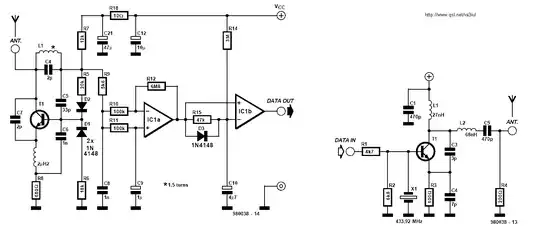
If you want complete DIY, which is probably not you best starting point, then something like this is about as simple as you can get. Receiver at left. Transmitter at right.

enter image description here

That is from this wonderful page of RF ideas Homebrew RF Circuit Design Ideas These tend to be circuits only with no notes so a bit of a leap for a beginner.

with the actual circuit diagram here


A wireless doorbell may do what you want.


"ASK" RF data modules abound - finding them amongst the 1000 at a time Alibaba adverisers is the trick.

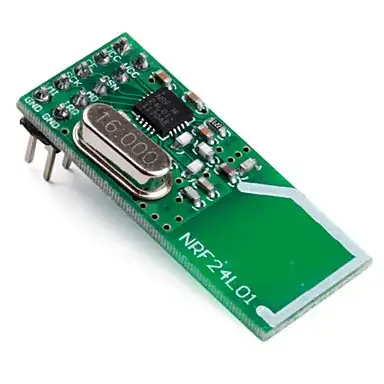
Here is one at $US6 with free shipping Uses nRF24L01 transceiver IC from Nordic.

enter image description here

From Sparkfun - uses same IC - $20.

  • Description: The nRF24L01 module is the latest in RF modules from SparkFun. This module uses the 2.4GHz transceiver from Nordic Semiconductor, the nRF24L01+. This transceiver IC operates in the 2.4GHz band and has many new features! Take all the coolness of the nRF2401A and add some extra pipelines, buffers, and an auto-retransmit feature - very nice!

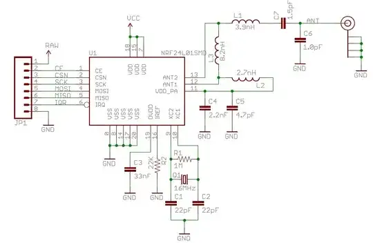
You can DIY it with the IC, burt here's what's on board (+ a power supply) enter image description here


There are many low power short range low cost wireless data modules available.

A large number of idea starters here look for small unhoused modules.

A bit fancy but would do what you want - but also somewhat complex to use and at GBP13.50 a bit expensive Pololu Wixel

Similar


433 MHz ISM band transceivers. $15US/1.here

enter image description here


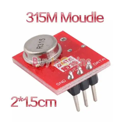
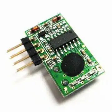
Transmitter $3 free shipping. Receivers will be ~ similar here

enter image description here


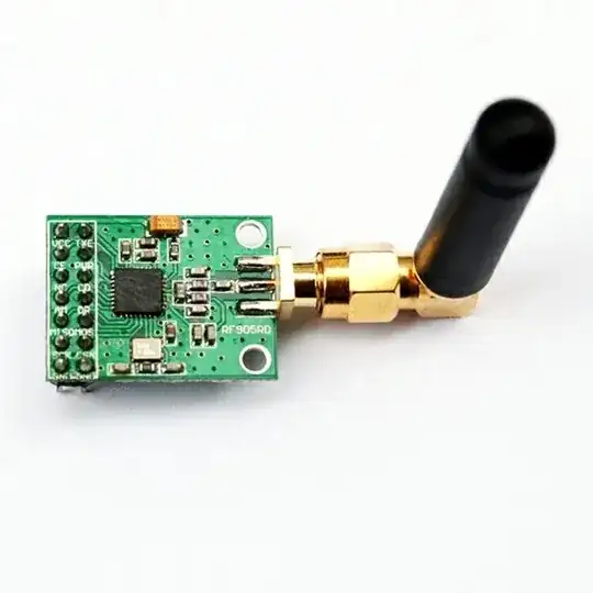
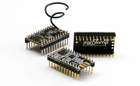
panStamp here

Open source

  • panStamps are small wireless modules programmable from the Arduino IDE. Each module contains an Atmega328p MCU and a Texas Instruments CC1101 RF interface, providing the necessary connectivity and processing power to create autonomous low-power wireless motes. Everything contained into a compact DIP-24 module.

Store $18.55 basic unit.

enter image description here


Units like this rare widely available at modest cost. This site only sells them in volume (probably).

enter image description here

B Seven
  • 125
  • 8
Russell McMahon
  • 147,325
  • 18
  • 210
  • 386
  • You mention a lot of short-range solutions but do you recommend any long-range (km or miles)? – Joe Phillips Jul 07 '17 at 16:24
  • @JoePhillips That's a 5 year old question that asked for short range solutions. Some of them have ranges out to some km. BUT if your requirement is substantially different then asking a new question may be in order. You can refer to answers that are not close enough to your need as a guide. There is a large amount of equipment easily found with a web search. Once you've had a look tell us what you want to achieve, what you've found on the internet and why easily available cheap items from eg AliExpress or Ebay or ... do not meet your need. – Russell McMahon Jul 08 '17 at 10:03
  • Yeah... there's too much equipment found with an easy web search :) – Joe Phillips Jul 08 '17 at 16:47
  • @JoePhillips Apart from we not being utterly omniscient, you need to put at least some effort into presenting a "specification" or requirement for what you wish to achieve. Treating the site as a lazy mans way of getting people to read your mind tends to destroy the site's likely usefulness to you at an exponentially increasing rate. – Russell McMahon Jul 09 '17 at 11:58
  • Is the example from the answer's beginning really about as simple as one can get? H. Hertz's [original setup](https://en.wikipedia.org/wiki/Heinrich_Hertz#/media/File:Hertz_transmitter_and_receiver_-_English.svg) was not nearly as complicated, so maybe a simpler starting point is possible? – Chad Branzdon Jun 24 '23 at 14:13
  • @user342060 That could have been put "... as simple as you can get while meting regulatory requirements, not causing interference and/or equipment failure, and having a group of angry people around you out to several times your own successful communications range. Hertz's transmitter was a very wideband White Pink and Octarine noise generator and his receiver required substantial tranmitting power at modest range. People have been rescued from a shipwreck by a lashup transmitter of that style, and a slightly more elegant (but not by much) receiver - but "don't try this at home" :-) – Russell McMahon Jun 25 '23 at 05:36
21

What none of these guys tell you, are what basic building blocks RF circuits typically consist of. Oscillator-modulator circuit, filtering, amp-stage etc. The trick here is to encode the 1s and 0s into something smarter and more resilient to noise.

You mention no baseline of knowledge, so let me start you at the beginning.

The biggest differences between wireless and wired communication protocols are in the noise and the power of the emitted signal. You will have lots and lots of noise when going wireless, so you need to encode your data instead of just transmitting them.

An example of this is AM radio - Amplitude Modulated radio. You transmit a signal (called the carrier signal, for instance a constant 433 MHz carrier) and then you encode your 1s and 0s as amplification of the signal, so a 433 MHz wave with low amplitude is a 0 and high amplitude is a 1. You can do Frequency Modulation as well, where you adjust the frequency instead of the amplitude. This has other characteristics than AM and is affected by noise in other ways.

There are several ways to encode this information. This is called keying (AM can be called ASK, for Amplitude Shift Keying). You will also stumble across PSK which means Phase Shift Keying, where instead of changing the amplitude or frequency, you change the phase. This is smarter than AM and FM and can even allow for higher bandwidth because you can embed more symbols in the carrier.

This is just the modulation or the keying phase. To ensure data integrity, you should use some sort of protocol with proper signal coding. For instance Hamming or Reed-Solomon coding. As an example, you can transmit some percentage of redundant data, which will allow you to lose some of the data, and still recreate at the receiver - without having to retransmit.

This sounds pretty advanced because it really is. It requires a lot of in-depth analysis and math to get a DIY RF circuit up and running if you want more than just proof-of-concept.

I haven't talked about filtering-techniques, and this is another vital part of RF circuitry...

BTW an interesting thing I found out when I researched keying techniques: 802.11 WiFi will change the keying and encoding scheme as the link signal strength fluctuates. It will use denser keying schemes and less redundant data with good signal strengths, to optimize the transmission scheme to the environment it's transmitting in. This sort of hardcore optimization is a pretty good reason why you shouldn't be afraid of using a commercial RF IC. Somebody has put a lot of thought into it, and it really is advanced stuff. Well, at least to me it is ;)

EDIT:

I've asked the same questions you are, and I've found that RF has such high barrier to entry, even on the web, that you won't get far without learning some theory first. At least enough to know and recognize the abbreviations, but also the mathematical skill and tools like Matlab or Octave. It's non-trivial to DIY-compete with what you'll get for say $10 at your electronics pusher :)

This page has some basic info on RF circuits

This page has a math intro on I/Q analysis.

EDIT2:

It's non-trivial to DIY-compete with what you'll get for say $10 at your electronics pusher :)

This is more likely $1-5 now a days on eBay. I've bought a lot of the simple 433/415MHz ASK-modules for $1 per receiver/transmitter pair. The more advanced modules are a bit more expensive, but RF circuitry has become very cheap.

Morten Jensen
  • 966
  • 1
  • 8
  • 18
  • "BTW an interesting thing I found out when I researched keying techniques: 802.11 WiFi will change the keying and encoding scheme as the link signal strength fluctuates." So, what is the keying of currently used 802.11 b/g/n where can I find a description? – dnnagy May 19 '17 at 11:52
8

Library. Check out a copy of any edition of The Radio Amateur's Handbook published in the last 30 years. It will teach you everything you need to know about RF for probably the next year or so. It truly is one of my favorite electronics books of all time.

lyndon
  • 4,366
  • 1
  • 16
  • 11
7

For research an education? Why not start with an AM transmitter and use an AM radio as a receiver. It doesn't get any simpler or cheaper to make than that :) Here's a simple one: AM transmitter

You can just use any old AM radio you have lying around to receive. Then you can make yourself your own AM transmitter AM receiver

If you can get that to work you can modify it to turn a light on instead of sending music or voice. That might not be how say home automation devices are made, but if you're trying to learn or teach, the AM radio will introduce you to the fundamentals of how this all works.

Edit: I knew I had a book on this but I had to go find it. Complete Wireless Design by Cotter Sayre. I see someone in the comments on amazon also recommended: Experimental Methods in RF Design which looks interesting but I do not have it myself.

Have Fun!

Whit3rd
  • 7,177
  • 22
  • 27
Some Hardware Guy
  • 15,815
  • 1
  • 31
  • 44
4

You're venturing into a complex area. If you REALLY want to proceed, take a look at XBee. You do not want to try to do this by yourself as a beginner. There is no shame in using prebuilt modules for complex tasks.

Matt Young
  • 13,734
  • 5
  • 34
  • 61
4

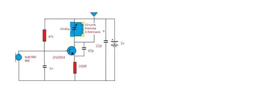
I will simply say, build a simple 1 transistor transistor transmitter first, e.g. below: I built this and it transmits approx 30M through FM radio. Tuning is at best difficult, and requires much patience. I don't normally offer this to beginners, but build the receiver the same way except with the "tank" circuit fed into the base of the transistor. The tank is the coil and the capacitor shaded in blue. Both tanks MUST be tuned to match frequency or it will not work. TIP! Read... Read... Then Read some more. If you seriously want it to work, buy a low cost frequency meter. E bay!! There are plenty circuits if you will Google "1 transistor receiver under Images" I have 25 years experience and can tell you, you picked a very complicated place to begin learning electronics. This circuit is very fundamental but works. You should really research RC and Filter networks because tis the key to success! I don't mean to sound discouraging, but ask any engineer and they will tell you that it is easy to build a transmitter or receiver that do not match frequency. The hard part is frequency drift, as a beginner is concerned. Hint! Crystals? Good luck! :)

SIMPLE TRANSMITTER

Mike H
  • 41
  • 1
3

I think I am late in answering this question. I was exactly in your situation about 2 years back. I started with RF to learn electronics. And oh my god, what a journey it has been so far. I also have to maintain a day job to put food on the table. So let me brief you what is needed. I made the choice that I won't use any prebuilt module.

1) What is the frequency of transmission. I planned 200 MHz, but later moved down to 60 MHz. Check 2nd step.

2) Why because once you start putting the components together you will notice that the capacitors, and inductors are not behaving as expected. Besides you will face lot of parasitic capacitance. Building a consistent local L-C oscillator is just tough. you will face lot of noise, I mean lot. Also you will have overtones (harmonics) in frequency. You need solid knowledge on Fourier transform, and poles-zeros. How they give you resonance. Also here you need to know about feedback, esp. positive feedback. Books generally teach you about negative feedback, but hardly positive feedback (even if they do, they tend to be brief). Designing a stable oscillator will call your thorough knowledge on almost entire analog electronics.

3) OK. So you have a stable oscillator, now you need to design your antenna. As I said, lower frequency implies higher antenna size, and vice-versa. While designing antenna on your own, you need to be thorough on transmission line theory and electromagnetism. Assuming you are in HF/VHF. If you want to go to Microwave region ( > 1 GHz), you need to know about waveguides. In designing your antenna, you have to very careful about feed-point design so as to make sure you have a balanced radiation (e.g. Dipole Antenna). You may need to learn softwares such as 4NEC2, its free and extremely good.

4) So you have the antenna and oscillator. Now you have to create your signal, and send it. Assuming you want digital communication. In that case, lets first talk about creating baseband signal and modulation.

4-a) Say you want to send a Byte of data. Very first thing you have to decide on is whether you want synchronous/asynchronous one. By which I mean the local sine wave oscillator (stage 2 above) are in phase or not. Say we want asynchronous one, say screw phase (don't take it literally though, phase is an extremely important concept). Now the data has to be modulated. You can use many modulation techniques (try Digital Communication by Haykin, check the chapter on passband transmission). This is a hard topic. You also need to come up with a method to sync clock in both transmitters and receivers, irrespective of whether you want sync/async communication. You can be clever and try some modern dsPIC microcontrollers here.

4-b) Now lets talk about sending. As you know you can't send signals at very low frequency (say 20 KHz). You have to shift the signal to much higher frequency. and you need to know something called Mixer. Here you would have to shift the frequency up(down).

5) Did I talk about filtering. You have to remove noise from signals via DSP. Here you need to know about filtering theory. You may implement FIR/IIR filters. You need to be really solid in Mathematics, signals and systems at this stage.

6) You need to be good in hardware programming as well, as you will be programming DSP processors (e.g. dsPIC).

Please remember this is very broad idea I am giving. You need to be very hands-on on soldering circuits on general purpose PCB. Here you will face concepts such as parasitic capacitance, ground plane all of which can ruin your system.

Good luck. You have chosen the right area to start, you would have hell of a tough time, but man if you do it all correct, you will be one hell of a person.

My project is still not complete, its ongoing.
niki_t1
  • 281
  • 2
  • 14
  • This is a very poor answer, heavily conversational, short on facts, and mixing up concepts in a way that has been confusing subsequent readers. Please consider deleting it. – Chris Stratton Oct 10 '20 at 15:29
  • 1
    @ChrisStratton please put a better answer, as the current answer is upvoted, I can't. Here is the idea - please layout a better answer, and I will delete my answer. – niki_t1 Oct 12 '20 at 03:41
  • As this is not an "accepted" answer nothing prevents deleting your posting. This page already has a far better answer. – Chris Stratton Oct 12 '20 at 03:44