8

I'm trying to make a velocity-sensitive keyboard for playing music.

I have to measure the position of each key in order to know how loud the sound should be.

The volume of the sound is a function of the velocity of the keys at the end of the descent. I know the position can be recovered from the velocity by integrating it.

What would be the cheapest and easiest, yet still reasonably precise way to do it?

I don't know exactly what “reasonably precise” would mean in the context. I'll have to test it.

The length of the maximum displacement is about 2 cm.

EDIT: not as some answers seem to suggest, the loudness is NOT function of the mean velocity of the key.

EDIT2: The loudness is function of the hammer speed at the moment it hits the string, but the key isn't pushing the hammer until the end of its path. It is really like throwing a ball on a wall: the ball leaves the hand at one moment, before it hits the wall.
Jonas Daverio
  • 632
  • 5
  • 17
  • 4
    You could use an IR-diode and a photodiode next to each other below the key, the photodiode measuring the reflected light. The lower the postion of the key, the more reflected light reaches the photodiode. Then convert the photocurrent to a voltage using a transimpedance amplifier. You will have to play around to see what voltage or voltage change corresponds to which volume. – jusaca Mar 24 '19 at 13:07
  • Have you considered putting an accelerometer on each key? Integrating acceleration gives you velocity, and integrating velocity gives you position. Since you're dealing with short distances & time periods you could probably ignore the accelerometers' small offset errors. – brhans Mar 24 '19 at 13:11
  • Are you familiar with Launchpads? – cat Mar 24 '19 at 14:08
  • 1
    @cat I'm familiar with Launchpads and I still have no idea what you are talking about. Can you be a little more helpful? – Elliot Alderson Mar 24 '19 at 14:48
  • @brhans With dozens of keys, I don't see how this solution could be economical. Correct me if I'm wrong. – Jonas Daverio Mar 24 '19 at 17:31
  • 1
    Yes I believe you are wrong. Compare a [$1 accelerometer](https://www.digikey.com/product-detail/en/stmicroelectronics/LIS2HH12TR/497-15069-1-ND/5043075) to an individual mechanical sensor on each key. Think of the reliability from zero moving parts (assuming you do the interconnects properly). You would need a reasonably capable microcontroller and a little experience writing firmware to pull it off though. – brhans Mar 24 '19 at 18:30
  • 1
    @jusaca looks like that's already a product on the market: https://deskthority.net/wiki/Adomax_Flaretech :) – flaviut Mar 24 '19 at 19:46
  • I don't think 1$ to be really cheap. But there is maybe no other cheaper solution. – Jonas Daverio Mar 24 '19 at 20:54
  • There used to be regular alpha keyboards that used capacities sensors rather than resistors. "Contact" was sensed by detecting an AC signal. Such a scheme could in theory detect the rapidity of contact, with proper detecting logic. – Hot Licks Mar 25 '19 at 02:11
  • @brhans MEMS accelerometers are actually "Micro Electronic *Mechanical* Sensors". – vectory Mar 25 '19 at 22:15
  • @vectory - I've been using them for almost 20 years. I know what MEMS means. What I'm not clear on is what your nit-picking over terminology achieves. – brhans Mar 26 '19 at 00:09
  • @brhans Great for you, I haven't though, so demystifying the slang is all I can contribute. Your notion might be valid otherwise, and the fact that a rotary with what, 30k turns life-time, or more for the appropriate price, might might wear out sooner or later is surely notable. – vectory Mar 26 '19 at 00:20
  • Musical instruments (aka "keyboards") are doing this kind of sensoring for ages. Did you research how do they do it? Patents? Anything? – Ale..chenski Mar 28 '19 at 18:46

9 Answers9

17

Most keyboards simply use two contacts per key, configured so that they close (or open) at different positions in the key's travel. They estimate velocity from the time that elapses between the two events. Even the fancy weighted "piano action" keyboards use this basic sensing method.

Trying to measure position and/or velocity directly sounds like massive overkill.

Dave Tweed
  • 168,369
  • 17
  • 228
  • 393
  • 3
    I think this method is insufficient. Here's why: if I slowly push the key down half of the path, and then quickly push it down to the end, the sound would be loud on a real piano, and this method would think the key was pushed really slowly and therefore output a really quiet sound. In addition, if I want to repeat a note, I would have to let the key completely return to its original position, which is not at all what I would do on a real piano. – Jonas Daverio Mar 24 '19 at 17:26
  • 10
    If one contact was at the bottom and the other contact was very near the bottom, you would not have this problem. – George White Mar 24 '19 at 17:40
  • I think George White's remark is quite close to a real piano: when you press a key half way and release it you wont hear anything either. And to repeat the same key you only need to lift the key very little: perfect for La Campanella :) – Huisman Mar 24 '19 at 18:23
  • @George White I didn't think of that. But imagine that you press a key really fast untill the middle, and then really slow. By the middle, the hammer would already be realised, and you would hear a loud sound. – Jonas Daverio Mar 24 '19 at 20:52
  • 1
    Every real instrument has its nuances and limitations. Musicians develop techniques to exploit these for musical effect. The player will soon learn to carry through to the bottom of stroke to get the desired effect. – Transistor Mar 24 '19 at 21:07
  • @JonasDaverio The solution to your problem is the combination of this simple sensor and weighted keys that have that inertia you're looking for, I think. – Hearth Mar 24 '19 at 21:10
  • 1
    @Transistor Yes, indeed, but my goal here is to try to simulate as close as possible a real piano. There are already plenty of keyboards available, but I never found one that did that. There are probably some really expensive one, though. – Jonas Daverio Mar 24 '19 at 21:46
  • Well, at some point, your simulation will be indistinguishable from a real piano. What are you trying to accomplish here? – Dave Tweed Mar 24 '19 at 22:00
  • 1
    The point would be to have a midi output and the possibility to have more keys (for microtonality) while keeping all the sensation of a real piano. I know this will never be reached anyway. And I also want to keep it relatively cheap, but if I can't, I'll stick on the regular solution. – Jonas Daverio Mar 24 '19 at 22:59
  • But MIDI itself cannot represent the nuances you're talking about anyway. – Dave Tweed Mar 24 '19 at 23:02
  • 1
    Yes, it can. I'm talking about volume (loudness), pitch and duration. What I want is to determine all of those from the pressing of keys. – Jonas Daverio Mar 24 '19 at 23:58
  • 1
    @JonasDaverio the most expensive of digital pianos achieve their accuracy by actually having a movement with hammers, and measuring the speed of those hammers as they move and hit a "backboard" that stands in for the strings. They also cost $40,000USD... – mbrig Mar 25 '19 at 04:35
  • @mbrig Ok That's not what I'm gonna do. – Jonas Daverio Mar 25 '19 at 10:24
9

I have to measure the position of each key in order to know how loud the sound should be.

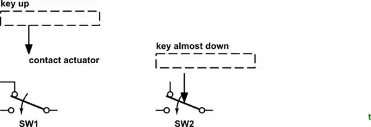
Normally key velocity is calculated by measuring the time between the normally closed up-switch breaking and the normally open down-switch making.

schematic

simulate this circuit – Schematic created using CircuitLab

Figure 1. A break-before-make keyboard contact is typically used for velocity measurement.

The volume of the sound is not only function of the velocity of the keys at the end of the descent. ... The length of the maximum displacement is about 2 cm.

In this case you need to mechanically arrange the normally closed contact so that it breaks in the last few mm of travel.

schematic

simulate this circuit

Figure 2. The mechanical switching arrangement.

It seems to me that your best bet would be to modify an existing MIDI bass pedalboard to suit your purposes.


OP's comment to Dave Tweed:

I think this method is insufficient. Here's why: if I slowly push the key down half of the path, and then quickly push it down to the end, the sound would be loud on a real piano, and this method would think the key was pushed really slowly and therefore output a really quiet sound. In addition, if I want to repeat a note, I would have to let the key completely return to its original position, which is not at all what I would do on a real piano.

That is why I proposed activating the changeover switch in the last few mm of travel.

Transistor
  • 168,990
  • 12
  • 186
  • 385
  • I responded back for why I think this is still insufficient. – Jonas Daverio Mar 24 '19 at 20:55
  • I think you misread what I wrote. I meant "The volume of the sound is NOT only function of the velocity of the keys at the end of the descent." – Jonas Daverio Mar 24 '19 at 21:48
  • Indeed, the energy depends on the speed over the time-length of the impact, which is a function of acceleration (and the jerk, if you don't assume constant acceleration). However, are sure that makes much of a difference? Can you characterize the specifics that you have or are looking for? I don't know what that would be. It might depend on the effect that it's supposed to have on the algorithm. – vectory Mar 25 '19 at 22:39
  • @JonasDaverio Are you referring to escapement? Digital pianos accomplish this with a third sensor that fires slightly above where the key bottoms out (and above the sensor that sounds the note). If the key does not go high enough to release this 3rd sensor, then bottoming out the key will not sound a second note, just like a real piano does not release the hammer unless the key is raised high enough. – DKNguyen Mar 25 '19 at 23:45
8

You should take a look at analog keyboards. Take a look at this video. This is just an example of concept.

Edit: Also, if optical switches are not working for you, take a look at this:

enter image description here

There is a PCB printed coil under each key cap. As you press the button coil measures the inductance change caused by key spring compressing and decompressing, therefore, you can get pretty accurate reading of the switch position.

Source:
Reddit
Imgur

Matt
  • 180
  • 1
  • 6
  • Apparently, they use a pair of IR-LED and photosensor: https://blog.wooting.nl/flaretech-the-optical-keyboard-switch/ However, I'm not sure wether they measure the delay between the emission and the detection or wether they measure the intensity of the light that could make through the tunnel. – Jonas Daverio Mar 25 '19 at 10:46
  • I linked that just for the example of analog keyboard. You can take a look at https://www.reddit.com/r/MechanicalKeyboards/comments/9ii6gw/this_is_my_first_unmodified_analog_cherry_mx/ and https://imgur.com/gallery/ImrH7nO . I'am not too familiar with the subject, just trying to help to push you into right direction :) – Matt Mar 25 '19 at 11:12
  • 1
    While this link may answer the question, it is better to include the essential parts of the answer here and provide the link for reference. Link-only answers can become invalid if the linked page changes. - [From Review](/review/low-quality-posts/217262) – Blair Fonville Mar 25 '19 at 11:22
  • 1
    @BlairFonville Fair enough. Let me summarize it. There is a PCB printed coil under each key cap. As you press the button coil measures the inductance change caused by key spring compressing and decompressing, therefore, you can get pretty accurate reading of the switch position. – Matt Mar 25 '19 at 12:12
7

If the important variable is the impact of a "hammer" that you're trying to emulate, consider piezo sensors which allow you to measure this directly. They produce a pulse whose amplitude depends on the impact impulse.

pjc50
  • 46,540
  • 4
  • 64
  • 126
3

One option could be Hall sensors, which sense the strength of a magnetic field. There are different types of Hall sensors for digital and analog sensing, you need one that has analog. For example SI7211 costs about 0.80 USD.

You also need a small magnet underneath each key. When the magnet gets closer to the sensor, the magnetic field increases which increases the sensor's output voltage.

jpa
  • 6,804
  • 17
  • 32
  • 1
    Apparently, they use it on some music keyboards. I think this is a really simple and good solution. I will compare the costs with 0xDBFB7's solution. – Jonas Daverio Mar 25 '19 at 16:46
2

You can treat this as a hybrid digital/analog instrument by placing microphones[1] inside the keyboard, tuned to the sound of striking the keys. Signals from the microphones augment the traditional switch-based input, so the switch tells you which key is pressed, and the microphones tell you how loud the most recent keypress was.

2 or more microphones along the keyboard's length would permit decoding a chord with loud/low notes and soft/high notes and vice versa.

[1]: I keep saying "microphone", but I mean "generic vibration sensing device".

Alex Shroyer
  • 1,310
  • 8
  • 14
  • That's pretty much how an E-Guitar works, I guess. However, the question didn't mention any acoustic parts, just keys. – vectory Mar 25 '19 at 22:32
2

How about capacitive sensing? Tape some aluminum foil to the bottom of the key, ground the bottom of the keyboard, and measure the rise time through a 100k resistor.

This method can be made almost arbitrarily precise, as long as your processor is fast enough to discriminate the change in capacitance.

I didn't explain the circuit very well. You connect a digital output to the key via a high value resistor, set it low to discharge any stray charge, and then set it high. You also connect a digital input directly to the key. The capacitance will slowly charge through the resistor, and you time how long it takes before the digital input turns on. This time is equal to the RC time constant of the circuit.

George White
  • 473
  • 3
  • 8
0xDBFB7
  • 913
  • 7
  • 24
  • So, I would have to pass AC in it, wouldn't I? – Jonas Daverio Mar 24 '19 at 23:53
  • 1
    @JonasDaverio I'm not sure what you're connecting the keys to, but one GPIO per key would suffice. – 0xDBFB7 Mar 25 '19 at 01:19
  • I'm not sure how I am supposed to measure the capacitance. One plate is connected to ground and the other is connected to what? A constant voltage source? – Jonas Daverio Mar 25 '19 at 11:29
  • 1
    The Teensy LC microcontroller[1] has 11 capacitive sensing inputs and a C++ library that makes it as easy as calling `analogRead` in Arduino. [1]: https://www.pjrc.com/teensy/teensyLC.html – Alex Shroyer Mar 25 '19 at 14:12
  • 1
    @JonasDaverio sorry, I didn't explain the circuit very well. You connect a digital output to the key via a high value resistor, set it low to discharge any stray charge, and then set it high. You also connect a digital input directly to the key. The capacitance will slowly charge through the resistor, and you time how long it takes before the digital input turns on. This time is equal to the RC time constant of the circuit. – 0xDBFB7 Mar 25 '19 at 14:50
  • @0xDBFB7 In fact, I calculated what order of magnitude this capacitance should be, and given that the surface of the key is in the range \$1\text{--}10\,\mathrm{cm}^2=10^{-4}\text{--}10^{-3}\,\mathrm{m}^2\$ and that the depth is about \$1\,\mathrm{cm}=10^{-2}\,\mathrm{m}\$ , and that \$\epsilon\$ is about \$10^{-11}\,\mathrm{F}\,\mathrm{m}\$ , which makes a capacitance of about \$0.1\text{--}1\,\mathrm{pF}\$ , which is very small. I don't know if it can be measured and distinguished from parasitic capacitance. – Jonas Daverio Mar 27 '19 at 02:20
  • @Jonas That is indeed quite small, though possibly still managable - with a 1M resistor, that takes 32 cycles on a 16 mhz processor. Changing the geometry slightly might help: the electrodes could be bent into two overlapping L shaped tabs, for instance, which would greatly decrease the spacing. I'd recommend some experimentation! – 0xDBFB7 Mar 27 '19 at 13:04
  • @0xDBFB7 But the first is that stray capacitance is of the same order of magnitude. The second problem is that the capacitance of the pianist would also be of the same order of magnitude. The change of shape could fix it by changing the ratio between stray/hand capacitance and measured capacitance? – Jonas Daverio Mar 27 '19 at 20:24
  • @JonasDaverio I think you'd find that the stray capacitance isn't really an issue, as it can be calibrated out or eliminated via judicious shielding. You could even have two plates, situated vertically, that overlap as the keys are pressed and have minimal separation - then the capacitance delta can be almost arbitrarily large. – 0xDBFB7 Mar 28 '19 at 00:40
  • If the capacitance of the pianist ends up being significant (I'm not too sure, since they're not going to be ground-referenced), extra grounded shielding can be added. – 0xDBFB7 Mar 28 '19 at 00:43
  • @0xDBFB7 Here is a reply from an other forum: 1. Calibration (or better, compensation) is possible only if stray capacitance doesn't vary, but it is going to be depend on the pianist's position. 2. It is possible in theory to compensate anything. In practice, in particular because of the measure repeatability, we tend to avoid having to compensate "to big" quantities (e.g. of the same order of magnitude or greater than the useful quantity) Example: if the measure is 10 and we have to compensate more than 5, it could be sensible to look at another test method. – Jonas Daverio Mar 29 '19 at 10:16
  • 3. I've indeed already suggested to shield the circuit. It will depend on the exact mechanism of the keyboard, but I doubt however about the possibility to implement an effective shielding that won't bring "too much" stray capacitance. – Jonas Daverio Mar 29 '19 at 10:16
  • @JonasDaverio I've used this technique to great effect even where the stray capacitance was several orders of magnitude larger than the signal. It's not like you're picking up noise, which is indeed much trickier to manage - it's just an offset to your frequency counter. Honestly, this circuit is so cheap and simple (1 resistor, 3 lines of code, some aluminium foil) that I would consider any more theory a bit of a waste of your time - just try it. If it isn't found to be serviceable, so be it - inductive is probably your best bet. – 0xDBFB7 Mar 29 '19 at 13:25
0

You may want to research spring return variable resistors, spring return potentiometers, or linear position sensors. Here is one example: http://ecatalog.beisensors.com/item/linear-position-sensors/linear-position-sensor-9600-series-compact-spri/9610r3-4kl2-0

Another possibility may be to use a small rotary encoder (and mechanically convert the linear key press motion to rotary motion). The encoder would output one or more sets of pulses as the shaft rotates. A higher pulse rate would indicate a higher velocity press. The encoder position could be tracked directly if the pulse groups are sent to additional digital logic. Here's an example part: https://www.mouser.com/ProductDetail/Bourns/PEC16-4220F-S0024?qs=6FD5PBp7ZtQte%252Bg7b%2FiMUw%3D%3D&gclid=EAIaIQobChMIrKbIjOSa4QIVCEsNCh3JAAKuEAQYAyABEgKM_fD_BwE

Nedd
  • 7,939
  • 15
  • 19
0

If you want super-accuracy at a reasonable price, how about using a linear encoder, attaching a Gray-coded strip (which you print yourself using a laser printer onto a transparent sheet, then cut up and attach one to each key) - more details of how they work under rotary encoders here. This way you need two (perhaps 3 so you get an accurate indication of end position) digital lines per key. This will allow you to measure velocity with very good accuracy and even position if that's relevant. The advantage of this is you could retrofit it to an old keyboard (even an acoustic keyboard).

Caution: when I was a teenager (a long while ago) I wondered for ages whether I could make a realistic keyboard more cheaply than buying them. It seemed unlikely then and it seems even less likely now. The cost effective method is therefore probably "buy a velocity sensitive keyboard and take it apart" which is no fun.

abligh
  • 367
  • 2
  • 9
  • 1
    Yes, I'm not pretending this will end up cheaper than a commercial one, but I'm trying to construct a special arrangement of keys that doesn't exist on the market. For your answer, I'm not really sure what you mean. Do you mean making a linear encoder from scratch? I don't understand what's the point of the transparent strip. And 3 bits seems a bit low to encode precisely the position and to deduce the velocity from it. – Jonas Daverio Mar 25 '19 at 10:56
  • A linear encoder will give you velocity with 2 bits only (see links) to a great resolution (you could get position to 256ths of the travel distance very easily). By timing the period between grey code bit transitions you will get a very accurate picture of velocity at different stages of travel of the key. 3rd bit gives you accurate 'hammer hits strings' signal. I was suggesting you use a linear encoder optical reader with your own 'tape' - transparent strip. – abligh Mar 25 '19 at 22:29