6

Possible Duplicate:
Can I use 10\$\mu\$F caps in a MAX232?

What is a decoupling capacitor and how do I know if I need one?

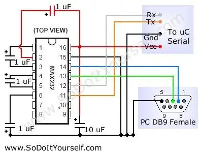
Kindly refer to the following typical MAX232 circuit:

enter image description here

I am still not quite sure I understand capacitors correctly, and while building this circuit, I realized that I wasn't understanding what the purposes of the capacitors I was sticking onto the breadboard were. My guess is that they are all used for power conditioning, or decoupling. I am not sure how I would be able to tell which one though.

I am especially confused about the 10 uF capacitor, as it seems like it's just shorting out the GND and VCC pins from my microcontroller.

capcom
  • 5,882
  • 14
  • 48
  • 59

4 Answers4

6

The 10uF capacitor shorts only AC voltages developing between VCC and GND: noise on the power supply. To DC, a capacitor is an open component!

When you power this MAX232 with single-voltage 5V supply, its V+ and V- pins are able to generate a dual supply: a positive voltage greater than 5V and a more or less equal but opposite negative voltage. How that kind of thing works is that an oscillator drives a network of diodes and capacitors: look up the term charge pump. The capacitors needed to make this charge pump work are connected to pins 1 and 3, and pins 4 and 5.

The 1uF capacitors on 2 and 6 (the V+ and V-) outputs, are just additional "rail caps" on this dual supply that is generated by the chip. They probably just do some further removal of ripple and noise from this generated supply. (To filter ripple, these capacitors don't have to be large. Why? Because the internal oscillator for the charge pump probably works at a substantially higher frequency than 60 Hz.)

The use of the capacitor on pin 2 shows a slight deviation from the "Typical Operating Circuit" given in the Texas Instruments datasheet (Figure 4). In the datasheet, the pin is capacitively coupled to ground through a 1uF capacitor. Here you have it coupled to VCC. That does not matter much, because both VCC and GND are AC ground.

However, this configuration is not a mistake. It appears in the original Maxim datasheets for this device!

One important clue in the TI datasheet is a note that this device is compatible with another company's existing product (and so is not a TI house design). It behooves us to look at the Maxim data sheet in addition to the TI one. That datasheet contains a lot more discussion and numerous additional diagrams.
Kaz
  • 19,838
  • 1
  • 39
  • 82
5

RS232 can range from +/-10V to +/-15V from what I've seen, and the MAX232 is used to convert from TTL levels coming from / going to a microcontroller, so its charge pumps needs the caps to get to the right voltage.

Dave
  • 3,800
  • 24
  • 41
2

I think they're just part of the voltage boost circuit and inverter circuits to get you those higher RS232 signal levels you need

Some Hardware Guy
  • 15,815
  • 1
  • 31
  • 44
0

The 10uF cap between supply and ground is a decoupling capacitor. It provides a low impedance charge buffer for the switched capacitor DC/DC converters inside the chip, which can have high instantaneous current demands.

The decoupling capacitor in this application is somewhat unique in that it's unusually large -- most digital ICs use a decoupling cap of ~0.01 - 0.1uF to ensure a solid power supply rail on die. In this circuit, the capacitor needs to source charge to the 1uF capacitors, so a 10x value is common.

HikeOnPast
  • 7,306
  • 2
  • 25
  • 20