19

I want to read high voltages, like ~50V, using a microcontroller. I plan to put this as an input into the microcontroller's A/D line. But of course, you shouldn't have voltage that high on the input of a microcontroller or it'll fry.

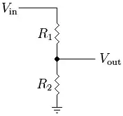
How might I read high voltages? The main thing is that I need to step down the voltage before reading it. What do I need to consider when stepping down this voltage?

Thanks in advance!

Edit: I noticed in the PIC18 datasheet that it says "The maximum recommended impedance for analog sources is 2.5 kOhms." How does this affect how I step down the voltage, be it with resistive dividers, etc.?

Jack
  • 499
  • 2
  • 4
  • 13
  • 1
    You mean **with** a microcontroller? The impedance note about analog sources probably means that if the sources are higher than 2.5K, the input on the PIC will start to load them down. You usually want a source impedance to be at least ten times smaller than the load impedance, so that it is not disturbed by the load impedance. This could be a roundabout way of saying that the input provides 25K of impedance. So we would make the voltage divider about 2K "tall". This means 25 mA will flow. If that's unacceptable, you can use a much more resistive divider, and high-Z buffer. – Kaz Oct 06 '12 at 00:52
  • 1
    Combining the answers below, I've used a resistor divider to step down the voltage and put the output of that resistor divider through a voltage follower op-amp. This op-amp then acts as a low output impedance buffer. This way, I can use high value resistors to limit the power loss in those resistors. – Jack Feb 27 '13 at 00:40

6 Answers6

26

A simple resistive voltage divider will achieve what you want.

Voltage Divider

The formula to calculate the output voltage is:

Formula

So if we assume your input voltage ranges from 0-50V, we need to divide it by 10 to achieve 0-5V. If we also assume we want to load the input voltage with 100kΩ, then the calculations would something like:

Vout / Vin = R2 / 100kΩ

0.1 = R2 / 100kΩ -> R2 = 10kΩ

R1 = 100kΩ - R2 = 90kΩ

So R1 = 90kΩ and R2 = 10kΩ

For an ADC requiring a maximum source impedance, you must make sure the voltage divider impedance is below this level. The impedance at the divider can be calculated as R1||R2.

For <2.5kΩ, the above won't meet this requirement as 10kΩ||90kΩ = 9kΩ
If we use 9kΩ and 1kΩ though, we get 1 / (1/1000 + 1/9000) = 900Ω

Bear in mind the lower the resistance the higher the wattage rating resistors you need. 50V / 1k = 50mA -> 50mA * 45V = 2.25W across the top resistor (0.25W across the bottom)
In these cases it's best to use an opamp buffer in between a high resistance divider and the ADC. Or use a 2kΩ and 18kΩ divider, which is not quite as power hungry as the 1k/9k version.

Oli Glaser
  • 54,990
  • 3
  • 76
  • 147
  • 4
    2.25W is a lot of power to waste doing a voltage measurement. – Nick Johnson Oct 04 '12 at 10:35
  • Yes, I agree - you would use the buffer mentioned (and elaborated on by Steven) in most cases. – Oli Glaser Oct 04 '12 at 10:39
  • 1
    50V/1k. How? Aren't those resistors in series? – Adithya Nov 25 '14 at 10:27
  • 1
    Same question here... how 50v/1k? Further where did this 45v came from? – Prasan Dutt Sep 01 '16 at 15:03
  • @OliGlaser not a word about capacitor? ADC input, if driven with high resistance, may distort the signal. Actually it does. So minimum is to use a small capacitor in parallel with lower resistor. –  Mar 01 '17 at 12:47
  • @GregoryKornblum - If you have a high impedance signal, then a buffer would be best as shown in Stevens answer. A capacitor would not help as it would create an RC (low pass) filter which would cause the higher frequencies in the signal to be attenuated. Unless of course you are measuring at or very near DC and you actually want to filter out any short term changes. – Oli Glaser Apr 05 '18 at 11:33
  • 1
    "very near" depends on numbers. And you anyway want LPF above your frequency of interest. –  Apr 05 '18 at 12:27
20

To add to Oli's answer:

enter image description here

The Schottky diode protects the opamp's input against overvoltage in case the input voltage would exceed the maximum specified 50 V. This is a better solution than the 5 V zener which is often placed in parallel with the 3 kΩ resistor. The 5 V zener voltage requires several mA, if the current is much lower the zener voltage will be lower as well, and the diode may clamp the input to for instance 4 V, or even lower.

The 27 kΩ resistor will allow 2 mA, isn't that enough for the zener? I might, but that's not what the zener will get; most of that 2 mA will pass through the 3 kΩ resistor, leaving only tens to hundreds of µA for the zener, which simply is too little.

Select a Schottky diode with a low reverse leakage current, so that the 5 V supply voltage doesn't influence the divider too much.

stevenvh
  • 145,145
  • 21
  • 455
  • 667
  • Forgive my naivety here but the Schottky diode protecting the opamp from an over voltage on the 50V rail, would this condition therefore raise the 5V rail? Thinking of doing this but concerned about other devices on the 5V rail (PIC, Arduino, etc) – GreenaGiant Aug 23 '18 at 20:25
  • Not if the current is small. Obviously if you connect low impedance source then the voltage will rise. But the 27k resistor ensures the current is small. – Martin Jan 23 '19 at 07:31
7

To fight your source impedance problem you could first use a voltage divider and then use a standard opamp. That should have a low enough output impedance for you. Here's an app note I posted yesterday on using opamps for converting voltage levels for ADCs.

http://www.ti.com/lit/an/slyt173/slyt173.pdf

Some Hardware Guy
  • 15,815
  • 1
  • 31
  • 44
6

For an isolated measurement, you can use a voltage transducer, e.g. LEM's LV-25 or similar.

But a much easier way if you don't need isolation is to just use a voltage divider:

enter image description here

Jim Paris
  • 2,685
  • 1
  • 12
  • 12
3

Look up something called a resistor divider. Using two resistors, you can multiply a voltage by a constant between 0 and 1. In your case you want to scale 50 V down to the microcontroller level. Let's say the micro is running at 5 V, so you want to scale the input by 0.1. This could be done with two resistors, the first having 9x the resistance of the second. The signal goes into the first. The other end is connected to the second resistor and the micro A/D input, and the other end of the second resistor is connected to ground. With the 9:1 ratio you get a gain of .1 (attenuation by 10).

You probably want the lower of the two (the 1x resistor) to be around 10 kΩ, which would make the other 90 kΩ. I'd probably use 100 kΩ to provide some margin and overrange sensing.

Olin Lathrop
  • 310,974
  • 36
  • 428
  • 915
1

I've successfully done this using a voltage divider and a Zener diode reverse biased between the input pin and ground (just in case).

s3c
  • 2,525
  • 2
  • 21
  • 31
  • 1
    A zener diode gives fixed output voltage and used for regulation. How you used it for varying input voltage? Sensor output voltage is varying between 0-50v and adc input should vary accordingly in between 0-5v. Using a zener will fix the adc input voltage. – Prasan Dutt Sep 01 '16 at 13:55
  • 4
    The zener is to protect the ADC input against voltages higher than the uC can handle, just in case, as he said. Let's say the uC can handle 0V-5V, if you plan to measure 50V, you put a 10:1 divider and a 5V Zener, so if the input goes over 50V, the zener clamps it to 5V. – s3c Sep 05 '16 at 15:06