7

I have a number of fluorescent lights installed that use 1-10V dimming. Note that this is not the same as 0-10V dimming as used in older theatre equipment.

The control gear for the lights outputs 10V on the two control wires. When open circuit, the light is at 100%. When shorted, the light is at ~10% (minimum level). Dimmer controls for this kind of lighting are passive devices, only connecting to the two connections from the fixture.

I want to be able to control this lighting digitally. I'm not too fussed with the protocol, as I can always program a µC to do protocol conversion. I have found commercially available devices such as this DMX 1-10V Converter, which will convert DMX/DALI etc to 1-10V, but they are rather expensive, and building my own would be much more fun.

Has anyone any experience with this control protocol? Or can you offer any pointers to where to get started?

Bill the Lizard
  • 264
  • 4
  • 15
colincameron
  • 518
  • 4
  • 13

2 Answers2

7

Basically what you are asking for is called a digital to analog converter, or D/A or DAC for short. In this case you want the full range to be 0-10 volts.

From your description, it appears the receiving end passively pulls up the line, and is expecting the dimmer to put a variable resistance between it and ground. You want to outright control the voltage, but you only need a low side active pulldown to do it. Here is a circuit that will probably work:

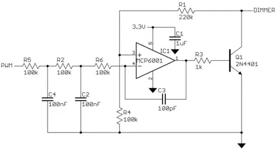
The input to this analog circuit is a 0 to 3.3 volt digital PWM signal from a microcontroller. R5, C4, R2, and C2 form a two-pole low pass filter that makes the average value of the PWM signal. Since your frequency requirements are so low, you can easily create such a PWM signal in a microcontroller with plenty of resolution. For example, a 1 kHz PWM signal will have its PWM frequency reduced by nearly 4000 (over 70 dB) by this filter. Even slow micros can give you 8 bits or more resolution at 1 kHz PWM frequency. The micro would adjust its PWM duty cycle in response to commands received via a UART or some other digital interface.

The opamp is used in the classic positive gain configuration, except that since the transistor inverts the signal the opamp inputs are flipped in response. R1 and R4 form the feedback divider, which in this case causes the circuit to have a gain a little over 3. Ideally you want a gain of 3.03, but the values shown give you a little bit at the top of the range where you know the output will go to maximum. The opamp drives the base current of Q1 to whatever it takes to make the desired dimmer line output voltage. R3 is there so that there will be some voltage change in the opamp output with output change. Otherwise, the opamp output would always be at the B-E junction drop above ground, which could lead to instability. You didn't say what the maximum current is that a dimmer has to sink. This circuit can handle well over 100 mA, which is probably high. If so, you can make R3 higher, but the 1 kΩ shown should work anyway.

C3 is there only for stability. You don't need much bandwidth, so there is no harm in overdamping the opamp. Some capacitance here will be needed since even with R3 there, there will actually be a voltage gain less than 1 from the input to the opamp output.

Edit:

The previous circuit accidentally had the opamp inputs flipped. The transistor inverts the voltage, so the opamp inputs have to be opposite from the usual positive gain configuration. The circuit above is now the fixed version.

I have also updated the circuit for the processor running at 3.3 V instead of 5 V and now show the PWM signal from the micro directly.

Olin Lathrop
  • 310,974
  • 36
  • 428
  • 915
  • Excellent answer, thank you very much. I understand most of the circuit from 3rd year analogue electronics lectures a couple of years ago, and your explanation filled in the rest well. Why did you choose the MCP6001 for this circuit? Would any rail-to-rail op-amp capable of working at the supply voltage work? My preferred µC is a 3v3 device, so I take it all I would need to change would be R1 to 220Ω to give a gain of ~3? – colincameron Oct 03 '12 at 14:18
  • 1
    @c.cam: I used the MCP6001 as example because it should work and I had the footprint already in my CAD system. Most rail to rail opamps that can run from the right voltage should be fine in this application. Yes, for 3.3V operation you need to increase the gain but little else needs to change. You need a gain a little over 3, so 220 kOhms for R1 sounds about right. – Olin Lathrop Oct 03 '12 at 14:52
  • @Olin, FWIW I simulated your circuit in LTSpice using an LT1677 opamp and the circuit oscillates. Using an LT1078 (much lower GBW) or LT1797 and it doesn't... adjusting C3 doesn't help... seems to be some sensitivity there. Of course that may not exist in the physical circuit, but something to look for. Also, the circuit inverts, so you must have an inverter on the PWM input for it to translate PWM duty cycle to current. As it is now, with minimum pulse width it gives you maximum current. Putting a simple 1-transistor inverter (or a single gate, or programming your PWM source to invert if it's – Marc Lindahl May 20 '15 at 00:33
  • @Marc: If you're going to simulate this, you need a load on the output, something like a 1 kOhm resistor to +10V. A physical inverter would be silly, just invert the value in the firmware. – Olin Lathrop May 20 '15 at 11:57
  • I'm looking to convert a 100-277V (wifi enabled) dimmer to 1-10V dimmer to power my led panel lights. Does this do the trick? Did you get it to work? I'd be willing to buy something if it was less than $100... thanks – swinefeaster Aug 09 '18 at 20:02
  • Interesting that by using a transistor instead of using the output directly you don't need to power the opamp with >10V. Much simpler design. – FarO Jul 17 '19 at 13:05
2

I have experience with this control protocol.

Few things to watch out for, whilst 10v is 100%, 1v is minimum output (not off as you might expect) so commercial "dimmers" include a mains relay to cut the power when your higher level protocol wants it off.

They don't have any notion of their own dimming curve (unlike DALI or DSI devices which are matched to human perception of brightness) so will need to put in your compensation.

They won't necessarily have their own galvanic isolation so you will need to add that as well.

back_ache
  • 351
  • 2
  • 9
  • Would you mind elaborating on your thoughts on 0-10V dimming? Do you have any alternatives to the accepted answer, or even, could you elaborate on what the circuit that creates the current source on the fluorescent/LED lighting drivers looks like? THanks! – SJoshi Mar 17 '15 at 05:14
  • Also, would you mind going into specifics on the output galvanic isolation? – SJoshi Mar 17 '15 at 05:14