2

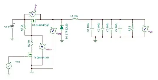
I have made this circuit but can't quit make it work.

  • Vext is my main supply from a car (9 - 14V)
  • Vbat is 8 AA batteries (10 - 13V)
  • Vout supplies power to a SMPS

As it is now, supply "fades" between Vext and Vbat when Vext is around the zener-voltage.

How can I make a clean cut between Vext and Vbat and a certain voltage, ie. 10V ?
battery backup

Brian_DK
  • 23
  • 3
  • In a circuit like this, one of the problems you have to deal with is that the battery voltage will rebound substantially when you remove the load from it. As the battery voltage declines, and you get to VBAT=10V, let's say you switch fast over to VEXT. The sudden drop of battery current will cause VBAT to very quickly rebound by perhaps 1V or more (depending on many factors). What should it do? A naive circuit will then be stuck switching back and forth between VBAT and VEXT as VBAT bounces up and down near 10V. – user57037 Mar 10 '19 at 01:03
  • What might make more sense is a priority circuit. As long as VEXT is present, VEXT will be used. Only if VEXT is absent will VBAT be used. – user57037 Mar 10 '19 at 01:05
  • It needs to switch over before Vext is absent. Otherwise the supply for the SMPS gets too low. Ie. during cranking. A switch-point of about 8-10V would be ideal. – Brian_DK Mar 10 '19 at 15:54

2 Answers2

1

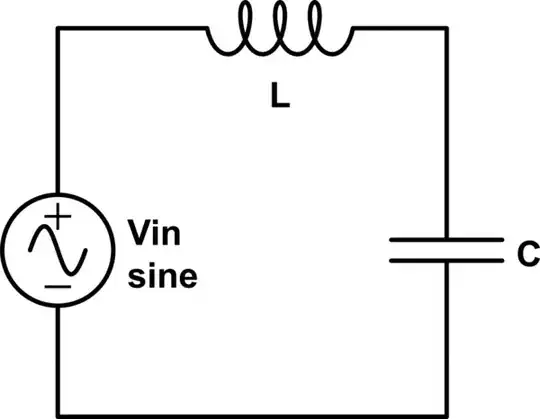
You can obtain a sharp (or at least sharper) transition between \$V_{EXT}\$ and \$V_{BAT}\$ respect to what happens in the current version of circuit by modifying it in the following way:

schematic

simulate this circuit – Schematic created using CircuitLab

In this circuit,

  • when \$V_{EXT}\$ lies below the threshold voltage level \$V_{th}\simeq V_Z+V_{BEQ_{1on}}\$, \$Q_1\$ is off and \$Q_2\$ is saturated: this implies that \$V_{GSM_1}\ll V_{GS_{on}}\$ \$\implies M_1\$ is on and thus the current flows from the battery to the load.
  • when \$V_{EXT}\$ rises above the threshold voltage \$V_{th}\$, \$Q_1\$ quickly goes on and \$Q_2\$ goes progressively out of saturation. The large gain of this two stage circuit forces a quick rise of \$V_{GSM_1}\$ even for relatively small values of \$V_{EXT}-V_{th}\$: so \$Q_2\$ goes quickly off, thus forcing \$M_1\$ off, since in this condition \$V_{GSM_1}\simeq 0> V_{GS_{on}}\$.

Notes

  • The large gain of the two-stage transistor amplifier is responsible for the sharp switching between the two power sources: however, note the that the switching speed of \$M_1\$ is controlled by its gate charge. If switching times of the order of nearly several hundred of microseconds are too much for your application, you should optimize the output circuit of \$Q_2\$ in order to reach the sought for switching speed.
  • If needed, you could change the \$Q_1-Q_2\$ amplifier layout to realize a Schmitt trigger: this is accomplished by connecting together the emitters of \$Q_1\$ and \$Q_2\$ and inserting a resistor going from their common node to reference ground. This may be useful if you need some hysteresis in the switching levels for \$V_{EXT}\$
Daniele Tampieri
  • 3,161
  • 4
  • 14
  • 29
1

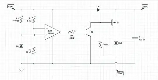
Another option is a comparator to stiffly drive the mosfet:

enter image description here

R1 and Dz simply set an arbitrary reference voltage (just needs to be less than the minimum VEXT), and the ratio of R2 and R3 can be picked to define the threshold voltage. The opamp is configured as a comparator, outputting a solid high or low depending on whether the input voltage is above or below the threshold voltage.

The rest of the circuit I borrowed from Daniele's answer to illustrate the point, but even it could be made simpler if you wish.

Note that if VBAT is less than VEXT turning on the MOSFET wont do anything, but I figure that's already part of your design.

Heath Raftery
  • 3,101
  • 1
  • 11
  • 16
  • +1. However, you should swap the two inputs of \$OA_1\$, otherwise \$Q_2\$ (and thus \$M_1\$) will be on when \$V_{EXT}\$ is high. Also I want to share with you a consideration: I think it is better to power \$OA_1\$ and \$D_z\$ from the \$V_{BAT}\$ since, from the context of the question \$V_{EXT}\$ seems to undergo larger variations, possibly including \$0\mathrm{V}\$, for relatively long periods. This implies that the reference voltage could fluctuate more than it is desirable. – Daniele Tampieri Mar 10 '19 at 09:18
  • 1
    Yeah, I had the same thoughts. I only chose \$V_{EXT}\$ as the power source to be sure the inputs were within the power supply range, but there's benefits the other way. I wasn't sure from the original question whether there were power consumption issues. – Heath Raftery Mar 10 '19 at 09:57
  • And if you have power consumption issues, powering \$OA_1\$ from \$V_{EXT}\$ is the best choice. +1, I confirm. – Daniele Tampieri Mar 10 '19 at 10:10
  • I've corrected the opamp inputs. Thanks for the catch. – Heath Raftery Mar 10 '19 at 10:17
  • Power from Vext in plenty, so no problem. Only requirement is that I would like the circuit to work with either of the V-supplies absent. As I see, M1 would be opened by Vbat if Vext is completely absent. Right? – Brian_DK Mar 10 '19 at 16:00