2

So I'm building a tachometer for my car. It's pretty simple, basically I have a wire wrapped around the spark plug wire about 10 times, and the 30-50k volts travelling through the spark plug wire should be sufficient to induce a small current through the wire wrapped around it. I'm detecting the voltage in an arduino and then doing a simple calculation to figure out the RPM.

So, I set this all up, and I have no idea where to put the ground. Now, if I just have one end of the inductor wire going to the arduino, through a diode and then voltage divider, the whole thing works, which doesn't make any sense to me, the other end of the inductor wire is just floating in the air, not connected to anything.

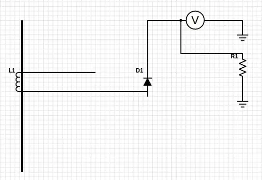
Here's what it looks like enter image description here

Thanks for any ideas. Like I said, this works, and it's giving moderately stable results, but I can't figure out why it works or how.

perilbrain
  • 695
  • 1
  • 6
  • 14
rozap
  • 131
  • 4

2 Answers2

3

Actually, you can't detect current in a wire by wrapping another wire around it. The magnetic field of the first wire doesn't couple to the second wire. If you think about it a bit, you'll realize that they're essentially at right angles to each other. Wires need to be parallel in order to couple inductively.

If you want to pick up the spark pulse inductively, as many timing lights, etc. do, you'll need to put a ferrite toroid around the ignition wire, and then wrap your sense wire around the ferrite (by passing it multiple times through the hole), too.

Dave Tweed
  • 168,369
  • 17
  • 228
  • 393
2

Your "inductor" is acting more like a capacitor in this application. In that sense, the circuit is being completed back through the wire, through the spark plug, through the ignition coil, to the ignition coil's ground.

If you wanted an inductive pickup, you would bring the other end of the sensing wire back to the Arduino-related circuits and connect it to the same grounds shown to the right of your illustration. But the current through the ignition wire is rather small, and it might require more turns of wire on your pickup. More importantly, this does not necessarily get rid of the capacitively-coupled high voltage pulse that's coming down the wire already. I'm surprised you didn't fry your circuit, so it's worth a lot that you say it works. Keep any protection circuits that you already have on it.

gbarry
  • 8,615
  • 21
  • 31
  • What sort of modification would I need to make to get it acting like an inductor? – rozap Sep 30 '12 at 21:55
  • Added to the answer. I think the signal you've got now is a lot bigger than the one you'll get inductively off of a few turns of wire. – gbarry Sep 30 '12 at 22:12
  • Alright, thanks for the explanation. I'm not entirely sure where the high current is coming from from a capacitive coupling, so I'll google that a bit. Thanks! – rozap Oct 01 '12 at 02:47