Apologies in advance for the long question, but I've hit a dead end trying to work through an interesting capacitor sizing problem. I'm hoping someone here can help.
Problem Description
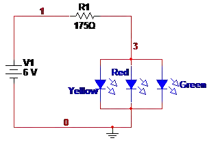
I have a variable current load consisting of several DC motors going through a pre-set run sequence. For the time period of interest, I have the load's current draw over time. This was calculated using the motors' torque requirements for this application, and it consists of many individual points separated at regular intervals across the sample period. This data shows that as you may expect, there are high-current spikes in the load current. I want to calculate the minimum capacitor size \$C\$ so that the capacitor voltage \$v_c(t)\$ never drops below 90% of the supply voltage \$V_s\$, assuming that \$v_c(0)=V_s\$. Below is a simplified diagram of the problem.
Schematic
simulate this circuit – Schematic created using CircuitLab
Known Values
- \$V_s\$ and \$R_s\$ are known
- Time of highest current spike \$t_{peak}\$ is known
- \$i_{load}(t)\$ is known at a sampling interval from \$t=0\$ to a point beyond \$t=t_{peak}\$
- \$v_c(t)\$ is known for two values of \$t\$:
- \$v_c(0) = V_s\$
- \$v_c(t_{peak}) \geq 0.9V_s\$
Assume that source \$V_s\$ can supply infinite current. Ideally, I would also like to know how to solve this if there is a current limit on \$V_s\$, but this assumption simplifies the problem.
Solution Attempt
I start by equating in and out currents at the node labeled \$v_c(t)\$:
$$ i_s(t) = i_c(t) + i_{load}(t) \label{kcl} \tag{1} $$
We know \$i_{load}(t)\$, and the other two values can be represented easily enough:
$$ i_s(t) = \frac{V_s - v_c(t)}{R_s} \\ i_c(t) = C\frac{dv_c}{dt} $$
Substituting into \ref{kcl}, we get: $$ \frac{V_s - v_c(t)}{R_s} = C\frac{dv_c}{dt} + i_{load}(t) $$
Rearranging, we get:
$$ \begin{align} \frac{dv_c}{dt} + \frac{v_c(t)}{R_sC} = \frac{V_s - R_si_{load}(t)}{R_sC} \label{origEq} \tag{2} \end{align} $$
I am attempting to solve this first order linear differential equation for \$v_c(t)\$, and use the conditions from the Known Values section to solve for a minimum capacitance \$C\$. To solve, we can first find an integrating factor \$\mu(t)\$:
$$ \begin{align} \mu(t) &= e^{\int{\frac{1}{R_sC}dt}} \\ &= e^{\frac{t}{R_sC}} \end{align} $$
Multiplying both sides of \ref{origEq} by \$\mu(t)\$,
$$ e^{\frac{t}{R_sC}}\frac{dv_c}{dt} + e^{\frac{t}{R_sC}}\frac{v_c(t)}{R_sC} = e^{\frac{t}{R_sC}}\frac{V_s - R_si_{load}(t)}{R_sC} $$ Using the product rule, $$ \frac{d}{dt}\left(e^{\frac{t}{R_sC}}v_c(t)\right) = e^{\frac{t}{R_sC}}\frac{V_s - R_si_{load}(t)}{R_sC} $$ Now, I chose \$0\$ and \$t_{peak}\$ as the bounds of integration because those are the two times \$t\$ for which I know both \$v_c(t)\$ and \$i_{load}(t)\$. Integrating, $$ \begin{align} \int_0^{t_{peak}}{\frac{d}{dt}\left(e^{\frac{t}{R_sC}}v_c(t)\right)dt} &= \int_0^{t_{peak}}{e^{\frac{t}{R_sC}}\frac{V_s - R_si_{load}(t)}{R_sC}dt} \\ \left.\left(e^{\frac{t}{R_sC}}v_c(t)\right)\right|_0^{t_{peak}} &= \frac{V_s}{R_sC}\int_0^{t_{peak}}{e^\frac{t}{R_sC}dt} - \frac{1}{C}\int_0^{t_{peak}}{i_{load}(t)e^\frac{t}{R_sC}dt} \\ &= \left.\left(V_se^\frac{t}{R_sC}\right)\right|_0^{t_{peak}} - \frac{1}{C}\int_0^{t_{peak}}{i_{load}(t)e^\frac{t}{R_sC}dt} \end{align} $$
I know that I can approximate the definite integral \$\int_0^{t_{peak}}{i_{load}(t) dt}\$ through a Riemann sum because I know \$i_{load}(t)\$ for this time period, but I can't evaluate the last remaining integral because the unknown \$C\$ is still present. Attempting integration by parts on this isolated integral,
$$ \begin{align} f(t) &= \int_0^{t_{peak}}{i_{load}(t)e^\frac{t}{R_sC}dt} \label{f} \tag{3} \\ u = e^\frac{t}{R_sC} &\implies du = \frac{1}{R_sC}e^\frac{t}{R_sC}dt \\ dv = i_{load}(t) dt &\implies v = \int{i_{load}(t)dt} \end{align} $$
This is where I've hit a wall. I can't evaluate the indefinite integral \$\int{i_{load}(t)dt}\$ because I only know \$i_{load}(t)\$ as a set of discrete points. If I try approximating \$v\$ as a definite integral \$\int_0^{t_{peak}}{i_{load}(t)dt}\$, then the integral \$f(t)\$ in \ref{f} evaluates to \$0\$, which I believe is incorrect.
Any ideas on where to go from here?