8

Is there any way to detect skin touching or no-touching between two people? Maybe using capacitive sensing or any other methods? It doesn't need recognizing gesture, only yes-or-no-touching.

The constraints are:

  • Two people in the classroom. (Each person may bring the sensor. If it only need one person, it's better).
  • Their gesture is in free way. (both standing, both sitting, one-standing one-sitting, or any gesture).
  • The size of sensor must not bigger than lunchbox.
  • The total price of the sensor components must below $100.
  • The sensor must be powered with battery.
  • The sensor output may only LED light. The light is on if touching detected.

I've read Touche for Arduino: Advanced touch sensing. Can this method be customized to detect person-to-person?

Passerby
  • 72,580
  • 7
  • 90
  • 202
  • Yes, it's possible by a number of means. But, you need to provide more context - in what environment is this to be used? And you need to say what "tough" means in this context. – Russell McMahon Sep 26 '12 at 03:33
  • I've updated my question. – raymondralibi Sep 26 '12 at 07:36
  • Does everyone else's heartbeat rise when you touch someone? – kenny Sep 26 '12 at 11:18
  • "Does everyone else's heartbeat rise when you touch someone?" It depends what she looks like. Seriously though I'd imagine it does at least at first, but you wouldn't be able to distinguish that from any other reason for heart rate increasing. – Some Hardware Guy Sep 26 '12 at 12:30
  • I will describe a fun experiment we made in physics class once. The teacher had hobby-made a voltage booster, powered by a single 9V cell. When person A presses a button, he gets shocked, unless he is standing on an insulating layer. But if he holds the hand of person B (A insulated, B - not) they both get shocked. And so on with 4-5 people. So what you are striving for **definitely** can be achieved :) – Vorac Sep 26 '12 at 13:08

4 Answers4

5

In case anyone comes looking, I've built something recently that did exactly this.

I built three versions, all of which work, but have different constraints in terms of what you're connecting to people.

1)Passive version One person has a wire attached to them. This is attached directly to the analog pin of the arduino.

If you repeatedly read from the analog pin of the arduino, you will get a pretty random value (basically the person is being a big antenna). However, the amount this value varies is pretty constant. So, I do analogRead 20 times, calculate the variance (you know, the obvious way, using your school maths). This stays constant while someone is not touching anyone else.

The moment they touch someone else, the antenna is one heck of a lot bigger, and the variance increases drastically.

2)Semi-active version

Both people have wires attached to them, person 1 is from analog pin of arduino, person 2 from ground of the arduino. The variance of an analogRead is repeatedly sampled. If the people aren't touching, the value shifts around, as before, and a high variance is shown. When people do touch, the circuit is grounded, and the value goes down to 0.

3)Active version

Both people have wires attached to them, person 1 from analog pin of arduino, person 2 from digital output pin. On the digital output pin, I output a square wave, in sync with my measurements of the analog pin. This way, when people touch, the variance is really high (as it is recording 0...1024...0...1024.) I use the pullup resistor to output the square wave, to limit current, don't know if it really changes much, but I felt more comfortable putting it through the person's body with it.

Because of the active signal being used, the top and bottom values of variance are pretty constant, so this version is I think most accurate.

The measurement loop looks roughly like this:

for(int n=0;n<20;n+=2)
{
    pinMode(outpin,INPUT);
    digitalWrite(outpin,HIGH); // square wave HIGH (through pull up resistor)
    delay(2); // let things settle + don't run analogReads too close together
    dataVal[n] = analogRead(inPin);
    pinMode(outpin,OUTPUT);
    digitalWrite(outpin,LOW);//square wave LOW (as output)    
    delay(2); // let things settle + don't run analogReads too close together
    dataVal[n+1] = analogRead(inPin);
}
// calculate variance of the data values here
Joe Marshall
  • 51
  • 1
  • 1
2

Check for resistance. 60MΩ or less is touching.

Ignacio Vazquez-Abrams
  • 48,282
  • 4
  • 73
  • 102
  • 4
    So one person has to hold one probe of a multimeter, and the other person the other probe? Doesn't seem practical, I don't think this is what OP wants. And what is special about 60Mohm? What's the difference between 55Mohm and 65Mohm? – Federico Russo Sep 26 '12 at 06:13
2

Just brainstorming a rough solution, I'd try something like skin impedance plethysmography across two people. Pass a low amp sine wave in the kHz range on one person. When you can detect it in the second person, there's contact. Plenty of caveats and obstacles to getting this functioning. The detection circuitry would drive your LED, but that's straightforward compared to the theory of operation.

Scott Seidman
  • 29,274
  • 4
  • 44
  • 109
2

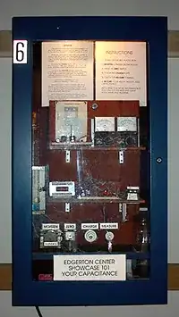
This contraption at MIT measures human capacitance.

enter image description here

It mentions:

a person's capacitance depends on many factors, including it's posture, its relative position, and its proximity to other electrically conducting things.

So you would measure the single person's nominal capacitance and then detect a change as another person (electrically conducting thing) comes in contact with the first. You would need to characterize the changes in capacitance of two people touching as well as one person changing posture or touching a metal plate or doing something else that may change their capacitance. Then determine if you can tell the difference between the various events.

The article states:

tall and/or heavy people have larger capacitance.

So I would imagine that two equally sized people touching would approximately double the measured capacitance.

That particular display is much larger than a lunchbox. But since it's purpose is to display the inner workings I'm sure much can be done to miniaturize it. They give a nice description of the apparatus but sadly no schematic that I could find.

When the user touches the electrometer input, the electric charge he or she is carrying is shared with a 0.06 mF capacitor. The voltage that develops across this capacitor is measured with a high resistance voltmeter, which uses an op-amp with an input resistance greater than 100,000 MW, resulting in a time constant of approximately two hours. For purposes of this display, the gain has been set to one, so that the reading on the digital voltmeter equals the voltage across the 0.06 mF capacitor. In words, the user's capacitance multiplied by 600 volts equals 0.06 microfarads multiplied by the digital voltmeter reading; the digital meter reading, in millivolts, equals the user's capacitance, in picofarads.

The display uses an adjustable, regulated low voltage power supply (ranging from 1 to 12 volts at up to 1.5 amperes), which powers an emitter follower connected to the primary of a transformer made by eight turns on a 5 mH ferrite core inductor. The secondary of the transformer is tuned to about 220 kHz by a capacitative divider which provides positive feedback to the transistor base. A half wave voltage doubler then yields DC outputs between 100 volts and 1200 volts at less than one milliampere. One analog voltmeter indicates the output voltage on the charging plate (approximately 600 volts), while a second analog meter, connected in series to the charging plate, acts both as a current meter and as a limiting resistor. By touching the grounding switch and the charging plate simultaneously, both meters will read about the same, with a small difference originating from the user's non-zero resistance. The grounding switch also serves to activate a relay that drains the 0.06 mF capacitor at the electrometer input, thus resetting the meter to zero.

embedded.kyle
  • 8,411
  • 2
  • 26
  • 44