4

I'm trying to go from 5 V, 1000 mA, which is a USB transformer for Apple devices, to 3 V, 750 mA (which is a small camera I have). I have purchased a NTE1904 3 terminal volatage regulator which 3.3 V, 1 A.

Do I need anything else like resistors to protect the camera? I see in various equations that there is an R1 and R2 on the output side of these things, but I have no idea if I need to put one inline before the camera and what size.

m.Alin
  • 10,638
  • 19
  • 62
  • 89
Ryantech
  • 41
  • 2
  • See related: http://electronics.stackexchange.com/questions/34745/choosing-power-supply-how-to-get-the-voltage-and-current-ratings – embedded.kyle Sep 25 '12 at 21:24
  • Hah that is the worst datasheet I have ever seen, well maybe not the worst but it's pretty awful :) I'm guessing that the R1/R2 you've seen on other regulators are just set resistors they're using to adjust the voltage. For example you could use them if you wanted to make a 2.3V regulator. – Some Hardware Guy Sep 26 '12 at 00:13
  • I agree with the guy below about heat sink and output cap, and you should probably also put an input cap as well. Especially since your power source is coming from a long cable. – Some Hardware Guy Sep 26 '12 at 00:15
  • With the resistors you can make the voltage only go higher, but not lower. So from a 3.3V regulator you can make only a 2.3V regulator if you have a negative voltage available. – hli Sep 26 '12 at 04:51

2 Answers2

2

I have though a Very Long Time about it, but I don't understand why you use a 3.3 V regulator if you want 3 V :-).

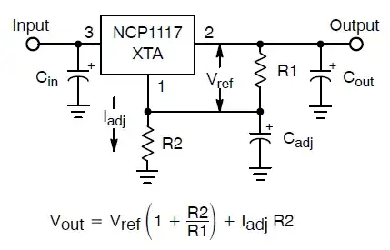
The resistors you mention are used with adjustable output voltage regulators to set the output voltage. Fixed 3 V regulators won't have them.

In any case you need an LDO (Low Drop-Out) regulator if your input-output difference is only 2 V. There are plenty of those these days, for instance the NCP1117 has become popular because it's used on Arduino boards. You'll have to use the adjustable version, because 3 V is not among the fixed output voltages.

enter image description here

This is where the resistors come in. You'll have a dissipation of (5 V - 3 V) \$\times\$ 750 mA = 1.5 W, which is a bit high for the 1117's SMT package, a TO-220 package will handle that much better. The MCP1826 exists in a fixed 3 V version, and has a junction-to-ambient thermal resistance of 30 °C/W, then at 1.5 W the temperature will only rise by 45 °C, which will be acceptable.

stevenvh
  • 145,145
  • 21
  • 455
  • 667
  • BYW- Thank you everyone for all of your help. I've ordered the NCP1117 and waiting for it.. In the meantime, I've hooked this camera up to my breadboard to test. I've tested the output of the NYE1904 and it's 3.25 volts. I've also gotten the output off of the Lithium CR2 3V battery that this was designed to work with andthe battery is putting out 3.24 (seems pretty close), however, the light go on but does not work. I've switched to the battery and it come up as designed. I read the spec of the camera and it said 750mA on the web so I though putting a 1A Voltage regulator would do the trick. – Ryantech Sep 27 '12 at 05:01
1

The data sheet says that you need an output capacitor of at least 2µF (10µF preferred), connected between the out and ground pin of the regulator. Since it's ESR shouldn't be too high, use either a low-ESR electrolytic (watch for the polarity), or a tantalum cap. According to the data sheet nothing else seem to be required.

Apart from that you should add a heat sink to the regulator, since it will dissipate about 1.3W of heat, and will get hot (especially in a closed housing).

hli
  • 2,336
  • 15
  • 17