I am taking comp architecture course, and we are given a task to write 32 bit look-ahead adder in VHDL. Instructor provided the instruction and diagram. While reading, Wikipedia article, I stumbled on the following diagram.
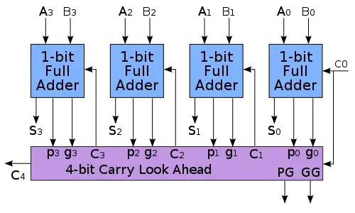
Since C4 is already available, what is the purpose of PG & GG outputs, ??? I am trying to find, if the instructors diagram is complete.
Thanks !
Asked
Active
Viewed 6,624 times
1
newprint
- 217
- 4
- 8
1 Answers
0
The block diagram of a 16-bit CLA is divided into four 4-bit groups and comprises a combinatorial circuit, namely the look-ahead carry generator. The term Gk denotes the group- generated carry, whereas Pk denotes the group-propagated carry. All four groups generate their individual internal carries and then the sum bits. The section-carry generate, GG, and the section-carry propagate, PP, are also computed.
travisbartley
- 4,823
- 3
- 23
- 41
-
First diagram is 32 bit CLA, made of two 16 bit CLAs. I understand purpose of `Pi` and `Gi`(where i is some number). But what can I do with `GG` and `PP` ? – newprint Sep 25 '12 at 01:44
-
1I think these might be useful for producing recursive adding. For instance, imagine a 64-bit adder with 16 4-bit groups and 4 4-bit CLAs. To compute the final sum, you could use a top-level 4-bit CLA which takes input from the the other 4 4-bit CLAs. So you can stack them hierarchically. If you only need a 32-bit adder the section-carry generate and section-carry propagate are not needed. – travisbartley Sep 25 '12 at 01:55