2

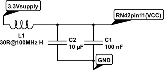
In the power supply design, there are always smaller value capacitors placed at the output.What is the main role played by these capacitors in the module? Check the screenshot attached and I am referring to C7.

schematic

simulate this circuit – Schematic created using CircuitLab

W5VO
  • 18,303
  • 7
  • 63
  • 94
IamDp
  • 1,865
  • 4
  • 26
  • 40
  • 1
    With smaller capacitors, you can create a mechanically-smaller loop, and reduce the inductance (perhaps greatly).This reduces the stored energy in a parasitic path, and reduces the amplitude of parasitic ringing voltage. – analogsystemsrf Feb 01 '19 at 15:13
  • 3
    overly-short explanation: one is built for speed (little one), the other is for power (big one). – dandavis Feb 01 '19 at 20:24

1 Answers1

5

That is done because the 100 uF capacitor isn't very "good" / doesn't work very well at higher frequencies. The 100 nF is much better at those frequencies, but has a smaller value so does not work for lower frequencies. The 100 uF capacitor takes care of those lower frequencies.

By using these two in parallel we create a "better" capacitor that works at both low and high frequencies.

It is explained in more detail by Dave from the EEVBlog in this video.

Bimpelrekkie
  • 80,139
  • 2
  • 93
  • 183