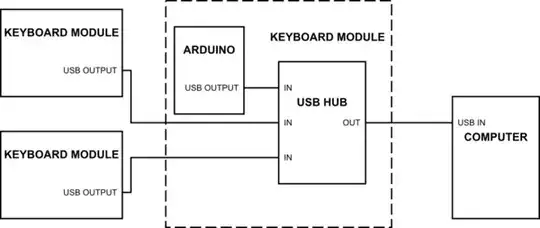
I'm working on a personal project which consists on a keyboard that also serves as a hub in order to connect more keyboards. For example, I could have the main keyboard with the letters and symbols and attach to this one another one that has the numbers. Another example could be a keyboard that is split into two pieces: left and right. The left piece will be connected to the computer and the right piece to the left piece. I know that most of the people do split keyboards using the I2C bus but I would prefer to use USB for better flexibility. The first challenge I have to solve is how to pass the signal from right to left. I have thought to use a USB HUB controller so each piece will have an Arduino micro which output will be connected to one input of the USB HUB controller and then the output of the HUB controller will be the output of the keyboard. The rest of the ports will be used to connect other pieces of keyboard or others peripherals.
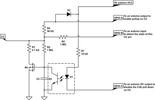
simulate this circuit – Schematic created using CircuitLab
Of course, all the keyboard modules will be built the same way so I can connect 3 of them in series and just the last one to the computer. I would like to have one input and one output in each side of the keyboard in order to get less messy with the cables:
The problem with this solution is that I would need a lot of USB type C ports and someone who is not used to this keyboard could connect output to output for example. The ideal solution would be to have just one USB on each side that can be used as input or output. So my question is: Is there a way to make a USB port IN or OUT depending on if it is giving power or receiving it? I was thinking to use the FE2.1 USB HUB controller and some kind of USB switch but I'm not sure if this is possible. Any suggestion will be appreciated.
PS: My experience in electronics is pretty low so sorry for all the stupid things I have said.If something is wrong or is difficult to understand just let me know and I will edit it.
EDIT 1
I have chosen the USB C because it's very thin (the keyboard needs to be portable), it does not care in which direction you try to connect the cable and, as far as I know, it's supposed to be more durable than the micro USB port.
The keyboard will be made by me, it's not an adapted keyboard so the Arduino will be used to handle the button matrix. All the keyboard modules will be made by me in the same way so all of them will have an Arduino and a USB HUB.
It's a personal project and I think that is more elegant to use just one USB per side (I will be spending some money and a lot of time in this project so I want it to be as good as I'm capable of). Using two different types of USB ports in each side is a solution but, if I can, I would like to have just one in each side.
EDIT 2
I think the best solution would be this one:
I would recommend looking a development kit for a usb type-c hub chip or chipset which is able to automatically switch ports from upstream or downstream, then you can leave all the gory details of usb-c to them and get on with building your usb peripheral.
And if I'm not able to find a usb controller like that or is too expensive this one:
just provide connectors on all sides and have them switch type host/device depending on where the power is coming from. (use USB switch chips)
I just want the connector to be USB C, I don't care which protocol is running under it. It's thought just to connect keyboards so anything should be fine.
