5

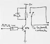
I currently have the following bit of kit: Photoplethysmographic sensor for measuring heart rate

It outputs a 5v pulse each time your heart pulses. What I need is to do is interface this pulse output to a keyboard (So each time your heart pulses a key is pressed on the keyboard).

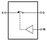
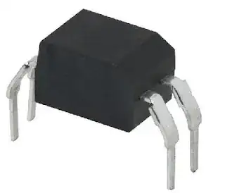
I have stripped an old USB dell keyboard and worked out what contacts on the keyboard PCB need connecting to simulate the key I am after.

I have drawn a circuit on how I think would be the right way to interface the two electronic circuits:

enter image description here

My question(s) are:

Will this circuit work as I intend it to?

Will the relay be able to switch on and off 50-120 times a minute?

Can you offer a better method of interfacing the circuits?

Scott
  • 286
  • 3
  • 10

5 Answers5

10

Whether a transistor directly across the contact is a good idea or not depends on how the low side of the switch is configured. If that's just an open-drain/open-collector then there's no problem. If it would have a very weak pull-up then the transistor's emitter will be a few volts positive with respect to the base, and though the voltage may not be high enough to damage the transistor, NPN transistors don't like that.

A safe alternative is to use an analog switch,

enter image description here

like the 74LVC1G66, which is an improved single gate version of the good old CD4066 quad switch. The 74LVC1G66 has an on-resistance of less than 10 Ω, but at least a few tens of ohms should be no problem.

Many of these switches have near-zero power supply current (typically 100 nA for the 1G66), and contrary to mechanical relays don't wear out.

If you can't connect the heartbeat monitor's power supply to the keyboard's you'll have to use an SSR (Solid State Relay), like Dave suggests in his answer. These are more expensive though: the Toshiba type Dave mentions costs almost 4 times the 1G66, so I would only use that one if you really need the isolation.

stevenvh
  • 145,145
  • 21
  • 455
  • 667
  • Thank you, I've never come across an analogue switch before. So just to confirm: I connect `S` and `D` directly to the keyboard terminals and `IN` directly to the output of the heart rate monitor? – Scott Sep 22 '12 at 15:15
  • Also as I need a 8pin DIP through hole package would this be a suitable choice? http://www.digikey.co.uk/product-detail/en/TS12A4514P/296-21908-5-ND/1629081 – Scott Sep 22 '12 at 15:16
  • 1
    @Brady - Two times yes. Make sure you have the TS12A4514, not the 4515, as the latter has a normally-closed contact. – stevenvh Sep 22 '12 at 15:36
  • @Brady - The simple analogue switch is the way to go for this project. Make sure that the GND of the sensor, the analogue switch and the keyboard are all interconnected. Also since the sensor runs on 5V, a USB keyboard runs on 5V and the analogue switch can also use 5V you should interconnect all of those as well. – Michael Karas Sep 22 '12 at 17:35
6

Your relay solution will work, but there are better options.

The analog switch suggested by @stevenvh is one, but it has the drawback that it requires that the grounds of the sensing circuit and the keyboard to be connected together, and you need to be sure that the voltage swing of the key-scanning signals remains within the power supply rails of the switch.

A small solid-state relay, like this one from Toshiba removes these restrictions, and like the analog switch, doesn't need the transistor driver; it can be driven directly by the output of the sensing circuit through a suitable current-limiting resistor.

Dave Tweed
  • 168,369
  • 17
  • 228
  • 393
  • This seems like a good alternative in case you can't connect your circuit to the keyboard's. (I don't know if that's a problem. Also this is 1.60 at Digikey, while the TS12A4514 analog switch Brady found is 65 cent.) – stevenvh Sep 22 '12 at 15:54
3

Many USB enabled microcontrollers have a virtual keyboard as a sample project. They also typically have a virtual serial port. You can even do it with software USB on general purpose micros such as VUSB on the ATTINY85. And then there are boards like the Arduino family which provide a serial channel over USB for applications to communicate.

While this can be higher cost than hacking a keyboard, it may be cheaper and simpler than the relay solution, or figuring out how to more closely integrate into the keyboard circuit. Directly hacking the keyboard is more preferable when you are using a custom physical switch as your new source of input.

Chris Stratton
  • 33,282
  • 3
  • 43
  • 89
1

I suggest you take a step back. Measure the voltage across key contacts, it should be non-zero. That's because a typical keypad looks like this: enter image description here

In this case, all you need is to connect the transistor's collector to the positive contact, emitter to ground and drive the base. No need for a relay.

Armandas
  • 7,845
  • 1
  • 32
  • 56
  • +1 for posting essentially the very same thing I was about to. A transistor between the appropriate row and column lines should do. – Alexios Sep 22 '12 at 14:23
  • 1
    A keypad may be connected this way, but a keyboard isn't. It would need more than 100 IO pins on the controller. A keyboard matrix is multiplexed. – Federico Russo Sep 22 '12 at 14:28
  • @FedericoRusso, will the solution I posted not work with a multiplexed keyboard? – Armandas Sep 22 '12 at 14:32
  • @Armandas as Federico said a keyboard is multiplexed. On the keyboard I'm using it sends out a signal in sequence on 13 pins and looks for a return signal on another 13 pins giving possible number of 169 keys. – Scott Sep 22 '12 at 14:50
  • @Armandas - it may or may not :-), see my answer. In the olden days 8048s were often used as keyboard controller, and those don't have real open-drain outputs. Maybe current keyboards aren't based on general-purpose controllers, I don't know. – stevenvh Sep 22 '12 at 14:58
  • I took apart a Dell keyboard looking to do something similar. There were no grounds or common lines. All matrixed. For best chances, go with any solution that doesn't have a common ground or any other connection from one side to the other. So, your relay should work, also the other suggestions for opto couplers and solid-state relays. Your mechanical relay may bounce, but so do keys, so I think the keyboard processor will handle that OK. 120 times a minute is twice per second--easy for a relay. – gbarry Sep 23 '12 at 07:06
1

I would go whith a optocoupler, it's a cheap single component that is isolated, fast, without noise, you don't need to worry with feedback current.

And it easily works near a hundred KHz

enter image description here

enter image description here

Vitim.us
  • 1,081
  • 1
  • 11
  • 14