1

I want to make a battery charger discharger with an arduino, to be able to plot graphs. And afaik N mosfets are better in terms of Ron and cheaper and easier to find. I have only N mosfets by the hand, so i decided to use only them, as a design restriction rule.

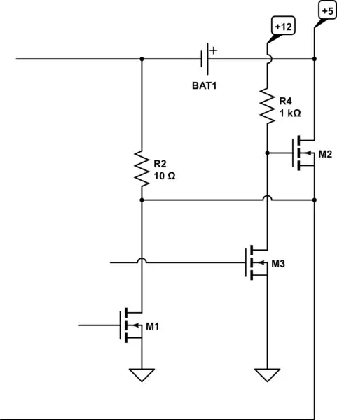
As a starting point i've opened a simple tutorial of charger, which offers following schematics:

enter image description here

Everything is transparent here: only one transistor, no magic with opening N-mos gate, and a 5V rail is constantly availble to Arduino.

However here are some drawbacks, that I dont know how to solve yet:

  • Major is that I totally stuck, trying to think of discharging circuit. I simply cannot short circuit 5V rail to the ground.
  • Minor is If 5V rail is disconnected from supply and charging is off there is no hope to start arduino from battery
  • Need to choose discharge current, I saw that variable CC-load is possible.

P-mos and changes to schematics could easily solve each. Is there a way to go for a design with N-mosfets only?


PS: Long ago, my math teacher used to say: "If it's impossible - why? If it's possible - how?", while posting an interesting task.

xakepp35
  • 395
  • 1
  • 14
  • you don't need to short the +5 got ground, only the bottom end or R2 needs to be connected to +5. That's going to be tricky to do with a N-channel-MOSFET because to do that you need a voltage higher than 5V for the MOSFET gate. – Jasen Слава Україні Jan 22 '19 at 03:54
  • @Jasen So, a P mosfet actually better fits here (as it requires gate pulled below). Thanks for remark. So you vote for it is impossible, or would require some boost converter? – xakepp35 Jan 22 '19 at 03:57
  • a boost converter could do it. but not easier than a P-FET – Jasen Слава Україні Jan 22 '19 at 04:17
  • @Jasen What if I add 12v rail as a power source? – xakepp35 Jan 22 '19 at 04:19
  • you stillneed to control the gate - you could use a resistor pull-up and another N-FET do that I guess. – Jasen Слава Україні Jan 22 '19 at 04:20
  • @Jasen But that is at least doable, that is great – xakepp35 Jan 22 '19 at 04:21
  • 1
    You may want to measure short term ESR and long term ESR which have different time constants using current sense and active loads https://electronics.stackexchange.com/questions/376850/how-determinate-parameters-for-thermal-model-battery-advanced-question-about-ba/376857#376857 It depends if you choose high or low side sensing and loading for Pch Nch options. Look at Battery Coulomb counter IC designs – Tony Stewart EE75 Jan 22 '19 at 05:01

1 Answers1

1

You don't need to short the +5 got ground, only the bottom end or R2 needs to be connected to +5. That's going to be tricky to do with a N-channel-MOSFET because to do that you need a voltage higher than 5V for the MOSFET gate.

g8ven a 12V (or 10V) supply in addition to the 5V supply it's possible.

schematic

simulate this circuit – Schematic created using CircuitLab

The 12V doesn't need to be strong, you could use the +10V from a MAX232 or build your own capacitive booster

a simple voltage booster can be made like this. it don't do a very good job the voltage is higly load dependant, but it's probably enough if you just want to turn a mosfet on or off.

schematic

simulate this circuit

  • Nice one, simple and clear. Where does `M2`'s source go? (far away to the bottom line) That's a "blot", I guess? – xakepp35 Jan 24 '19 at 15:09
  • Hovewer, having 2 voltages - this is too much. The 5V doesn't need to be strong - because it is only required for Arduino. And there could be even no 5V, because Arduino will just take it from USB port. Could I get rid of 5V here? If I have full 12V, and charge current could just be controlled by `M1`? Is that possible - single voltage rail + N-mosfets only? I wonder if maybe there could be a trick, "known only to old-school professionals" :) – xakepp35 Jan 24 '19 at 15:10
  • where does M2's source go? to M1's drain. that bottom line is the same as in the question. – Jasen Слава Україні Jan 25 '19 at 06:18
  • 5V is charging the battery, looks like about 200mA - you could use the USB perhaps. if you connect the battery to 12V in gets hard to measure battery voltage. – Jasen Слава Україні Jan 25 '19 at 06:20
  • I am making 8(eight channel) charger, for 18650, each battery is rated at 3000mAh each, recommended max charge current is 3A (`3*4.2` reuquires to reserve at least 12-13 watts per each battery channel for good charging), so i need at least 105 watt power supply. On the 5V line that will be whooping 21 Apms, wires are to be **very large**, and also its hard to find suitable PSU for such a needs. So I would like to use 12V rail instead, for power supply needs, and build my own charger, where each channel is programmed and logged (Perhaps, with better schematics) – xakepp35 Jan 28 '19 at 09:33
  • But you've answered my question, fully! Thank you alot! I was just looking for a starting point for experementation (with a single battery only). – xakepp35 Jan 28 '19 at 09:33