1

I have the following circuit:

schematic

simulate this circuit – Schematic created using CircuitLab

I need to determine period of oscillations for the given circuit and to sketch waveforms of the voltages at nodes n1, n2 and n3.

Values of the resistances and capacitance are known and OPamps are considered to be ideal.

$$R_1=47k\Omega\\ R_2=39k\Omega \\ R_3=10k\Omega \\ C=100nF$$

Basically, what I can see here, is that this circuit consists of an inverting amplifier in series with an integrator (correct me if I am wrong), but I really cannot see the way to sketch the waveforms required since I cannot see what is actually going on here.

Warren Hill
  • 4,780
  • 20
  • 32
cdummie
  • 217
  • 3
  • 10
  • 1
    hm, which one is the inverting amplifier? – Marcus Müller Jan 17 '19 at 16:24
  • I suppose the first one, or it is the non inverting one, since we have the feedback to the positive input, i am bit confused now actually. – cdummie Jan 17 '19 at 16:32
  • 1
    As @MarcusMüller is hinting, pay careful attention to your feedback polarity. What does that make the first circuit? – John D Jan 17 '19 at 16:32
  • Well, positive feedback to the positive input, then it should be non-inverting amplifier, does that make any sense? – cdummie Jan 17 '19 at 16:34
  • yep, so I went ahead and labeled your opamps (and I removed the "741", because the 741 is as far from an ideal opamp as you can commercially be); U1 is in a positive-feedback configuration. What does that tell you about the input-output voltage relationship? – Marcus Müller Jan 17 '19 at 16:40
  • well, in and out voltage should be in phase i suppose, but, how that can help me to sketch those waveforms – cdummie Jan 17 '19 at 16:47
  • @MarcusMüller -- normally I'd second you turning them from 741's into anonymous op-amps, but it matters in this case. OP -- that's a hint. What condition of gain and phase must be met for a circuit to oscillate? Can you see how those conditions are met with this circuit? – TimWescott Jan 17 '19 at 17:15
  • Well we need zero phase between loop gain and "regular" gain in order to have oscillations – cdummie Jan 17 '19 at 17:19
  • @TimWescott yeah, I know, but to cite the question: *OPamps are considered to be ideal.* – Marcus Müller Jan 17 '19 at 17:20
  • R3 is present twice in the schematic and R1 is missing. Which one should have been R1? – Peter Karlsen Jan 17 '19 at 17:24
  • @PeterKarlsen R1 is the one between + terminal of first opamp and node "n1" – cdummie Jan 17 '19 at 17:27
  • 1
    I've corrected your drawing for you. – Warren Hill Jan 17 '19 at 18:06
  • @WarrenHill Thanks, i appreciate that, can you help me with this circuit, i am supposed to sketch waveforms, at the particular points, i tried to simulate to see what happens, but here, i only get constant voltages, at every point, which is not something i expected, since this should be oscillator, right? – cdummie Jan 17 '19 at 18:11
  • Now that @MarcusMüller has corrected my thinking about the nature of the op-amps in your schematic -- either your instructor has erred, or it is a trick question. You know you need zero phase around the loop -- given ideal op-amps, does that happen in this circuit? – TimWescott Jan 17 '19 at 18:22
  • I'm not convinced this is an oscillator. It cant be a sine wave output as there is no frequency for which the loop gain has zero phase. – Warren Hill Jan 17 '19 at 18:53
  • @TimWescott Well, i don't know. How am i supposed to figure out if there are going to be oscillations based on fact that i have ideal opamps? – cdummie Jan 17 '19 at 19:00
  • 1
    Its a relaxation oscillator. U1 is operating as a non-inverting schmitt trigger. – sstobbe Jan 17 '19 at 19:42
  • 1
    For this to operate, positive and negative power rails are important (they determine the symmetry, and the U1 output). Assuming +10V, GND, and -10V for power rails, will be useful. – Whit3rd Jan 17 '19 at 19:49
  • @sstobbe: D'oh. OP: listen to the guy who can actually look at a schematic and read it (d'oh, d'oh, d'oh). – TimWescott Jan 17 '19 at 20:03

2 Answers2

1

Here are a few clues to get you going.

schematic

simulate this circuit – Schematic created using CircuitLab

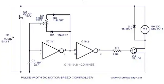
Figure 1. OP's schematic with U1 inputs labelled. It's not shown here but the circuit needs a split-rail power supply to work. e.g., +/-12 V.

Consider that the circuit has just been powered up. If everything was ideal then the op-amp inputs and outputs would be at 0 V and nothing would happen. Fortunately for this circuit real op-amps aren't ideal and have slight differences in the input offset voltages and this is enough to kick the circuit into life.

I've shown U1's non-inverting input at +1 mV and the inverting input, n0, at 0 V.

  • In that condition what will happen at n1?
  • What that initial change happens at n1 what will the voltage be at U1's non-inverting input?
  • Meanwhile what's happening to the voltage at n2? (Caution: trick question.)
  • What's happening at n3?

Sketch that part out and post a photo into your question and we'll go from there.


From the comments:

Well, when the input reaches high enough level we will have logic zero at the output of the Schmitt trigger.

This suggests some slightly mixed up thinking.

  1. This isn't a logic circuit - it's analog so while U1 can switch high or low they're not really 'logic' levels.
  2. You are correct if you mean that the output switches low but what is low in this circuit? (I gave you a hint in the caption of Figure 1.)

Also, I think that same thing should happen in n2 since those points are separated only by a single resistor.

No, n2 is what's known as a 'virtual ground' due to the negative feedback caused by C1. R3 controls the current into the integrating capacitor. If the op-amp output is not in saturation then the output will adjust to maintain n3 at (or very, very close to) the voltage on the non-inverting input, 0 V. See How does an op amp integrator work? where this is currently under discussion.

Transistor
  • 168,990
  • 12
  • 186
  • 385
  • Well, the first part of the circuit is schmitt trigger, so it is generating a pulse train at its output (node n1) i expect the same waveform at node n2, but i cannot see what will happen with the waveform after integrator in this case – cdummie Jan 17 '19 at 21:43
  • Schmitt trigger is correct but you haven't generated a pulse train yet. I have given you four questions. What is the answer to the first one? – Transistor Jan 17 '19 at 21:56
  • Well, when the input reaches high enough level we will have logic zero at the output of the schmitt trigger – cdummie Jan 18 '19 at 06:28
  • also, i think that same thing should happen in n2 since those points are separated only by a single resistor – cdummie Jan 18 '19 at 06:34
  • See the update. – Transistor Jan 18 '19 at 08:19
  • Low should be the lower threshold voltage of schmitt trigger, right? – cdummie Jan 18 '19 at 16:45
  • Nope. Low is the negative supply voltage, and when the Schmitt (note capitalisation) trigger output goes low it goes as close as it can to that voltage, -12 V in the example I gave in the caption of Figure 1. Your circuit will not work with a positive supply only. – Transistor Jan 18 '19 at 18:10
  • I know, i need to provide a negative supply too,but is the value of that negative supply voltage actually a voltage at n2 in the moment when Schmitt trigger input voltage is high enough, and it remains that way until significant change happens at the input? Is this right? – cdummie Jan 18 '19 at 19:49
  • No. n1 will switch negative. Read the response to your comments in my answer again. I explained that n2 remains at virtual ground. It never deviates more than a mV or so from 0 V as with any negative feedback op-amp configuration. Are you sure you understand how a simple op-amp inverting amplifier actually works? – Transistor Jan 18 '19 at 19:56
  • It was a typo actually, i meant to say n1 instead of n2. – cdummie Jan 18 '19 at 20:35
0

If the op-amps are to be considered as ideal, regenerative feedback will happen if both u1 and u2 are connected either both inverting, or both non-inverting