8

Lest's say that I have the following setup: a split supply (using two voltage regulators: a positive and a negative one) connected to a center tapped transformer (12-0-12). The output of the transformer is rectified. The center tap is the COMMON of the circuit. Except for the actual values the setup would be exactly the same as this one:

enter image description here

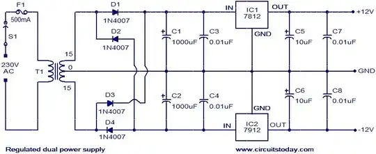
Please ignore the values. It is just to make a better picture about the setup.

I have two questions:

  1. In this setup, in order for everything to work properly, the current consumed by the positive rail should be approximately the same as the current consumed by the negative rail? Or it does not matter if one rail consumes less current than the other one. For example if the positive rail will consume 3Amps and the negative rail only 20mA will there be any problem? Will there be any noise induced in the circuit? Or any other bad things? :)
  2. How about if the transformer will have this setup: 12-0-5, so that on the negative rail a lower voltage will be used. Will it work properly? Or the two voltages of the transformer should be symmetrical?
Bruno Ferreira
  • 4,470
  • 2
  • 25
  • 36
Buzai Andras
  • 737
  • 4
  • 10
  • 20

2 Answers2

6
  1. The load currents do not need to be balanced. If they're not, it just means that there will be increased current in the center tap (ground return).

  2. The transformer needs to be symmetrical. Both halves of the transformer supply power to both regulators, on alternate half-cycles. However, it is not necessary for the regulators to have the same DC output voltages. They can indeed be different, but just be aware that the one with the lower output voltage will be dissipating more power for any given load current, since the input voltage is the same going into both regulators.

Dave Tweed
  • 168,369
  • 17
  • 228
  • 393
  • 1
    It looks like the issue with #2 is that since it's a full wave rectifier arrangement, and the diodes "cross over" to the "other side", that means that on one half of the cycle it would charge to 12 V, and on the other half, only to 5V. In practice the 5V half of the cycle would never contribute anything, and the circuit will operate as two half-wave rectifiers. – gbarry Sep 17 '12 at 14:38
-1

Output from each side of the transformer should be equal. The center tap of the transformer carries the unbalanced current of the circuit. If there is three amps on one leg and two amps on the other then one amp would flow in the center tap leg. This arrangement is a current device not really a voltage device.

  • 2
    "_Output from each side of the transformer should be equal._" This isn't true. See second diagram in https://en.wikipedia.org/wiki/Rectifier#Full-wave_rectification. There is no problem with drawing unbalanced currents on a split secondary. This point was addressed in the accepted answer over three years ago. – Transistor Aug 07 '16 at 18:45
  • Your answer also doesn't address question #2, which is answered in the current accepted answer. – user2943160 Aug 07 '16 at 21:04