0

I am new to PCB routing. In one of my projects, I need to be able to exchange data between nano-computers (https://www.variscite.com/wp-content/uploads/2018/01/DART-6UL_DART-6UL-5G_Datasheet.pdf) using an Ethernet connection. I will use a simple RJ45 connector soldered on my card (https://docs-emea.rs-online.com/webdocs/0fae/0900766b80fae0ad.pdf).

My question is now : how am I suppose to route the 8 Ethernet pins to my nano-computer ?

I do not want to route differential pair all the way to the nano-computer. I have searched and read about magnetics, transformers, rmii, PHY, MAC... But it is all confused in my head and I don't know which one I should use.

Is there a classic way to achieve this PCB routing ? (at least schematic routing first)

Thank you all

JackOfHearts
  • 649
  • 1
  • 6
  • 14
  • 1
    For additional info you can check NXP iMX6UL [original reference design](https://www.nxp.com/support/developer-resources/run-time-software/i.mx-developer-resources/i.mx6ultralite-evaluation-kit:MCIMX6UL-EVK) that contains all design files, and has 2 Ethernet ports. – Andrejs Gasilovs Jan 03 '19 at 10:01
  • Considering they probably just copied the reference design this is a very good source, upvoted. – Tom L. Jan 03 '19 at 15:26
  • Related: https://electronics.stackexchange.com/questions/90330/connecting-two-ethernet-phy-without-magnetics – Voltage Spike Jan 03 '19 at 16:22

3 Answers3

6

I think the routing is at the moment the least of your concerns. Usually, providers of SOMs also provide schematics for a base board. The least painful way to get a working board is to copy those schematics (at least the parts you require). I would guess this information is hidden behind the customer registration item on their webpage.

In any case, the module already contains everything including MAC + PHY (KSZ...) for one ethernet port according to their description, so you probably won't need those. I would guess (according to the pin description) that you would then route the pins to a transformer (1:1 winding ratio) and then to the actual connector. If you want to save on parts, you can get a connector with integrated magnetics (typically called magjack). Again, refer to the module's vendor on how to connect them correctly. The PDF is a little bit on the low information side.

If the track between RJ45 connector and module connector is very short, you can probably (!) get away with simply routing the tracks as you like. For everything longer, you will need to match the impedance closely to 100R Differential or 50R Single-Ended. Make sure that the trace lengths match at all costs.

Tom L.
  • 7,969
  • 1
  • 19
  • 34
  • What would be a very short distance ? On my actual board it will be about 10 cm. It might be considered long am I right ? – JackOfHearts Jan 03 '19 at 11:42
  • 2
    Yes, that's definitely long. Why do you have issues with differential routing? – Tom L. Jan 03 '19 at 11:44
  • This site : http://www.skottanselektronik.com/ section Differential Micro Strip gives me bad results with the following configuration : t = 0.035, h = 0.6, epsilon_r = 3.4. (h cannot be smaller) I want Z0 = 50Ohm and Zdiff = 100 Ohm To do so I need 1 mm long wires and separated by 5 mm... That's too much, I don't have this amount of space on my card. What solutions are left for me ? Do I really need to match the impedance for short distance ? (my wires are < 25mm) – JackOfHearts Jan 08 '19 at 13:59
  • That sounds wrong. Can you give us a description of your layer stackup (thickness, layers)? – Tom L. Jan 08 '19 at 15:11
  • I have found the solution. Maybe you can tell me if you think it sounds right. I based my calculation on this picture : http://www.skottanselektronik.com/d_mstrip.gif I can ask for a 0.6mm thick PCB. With a 4-layer PCB, and internal ground planes 0.0175mm thick, it gives me h = 0.1883mm. t = 0.035mm and cannot change. Then if I use w = 0.25mm and s = 0.267mm, I have as a result : Z0 = 57.05 Ohm and Zdiff = 100.06 Ohm which I think is satifying enough based on the set-up of my PCB :) – JackOfHearts Jan 09 '19 at 08:15
  • Again, post your complete stackup as that is what matters. That includes cores in used and dielectrics between the copper layers. Especially the vertical distances are important. Everything else is just guesswork. – Tom L. Jan 10 '19 at 19:41
  • My stackup looks like this image https://easyeda.com/Doc/Tutorial/images/4layerStackupPCB1oz.png except it's a 0.18 mm thick core – JackOfHearts Jan 11 '19 at 07:44
  • I calculated your requirements using the Saturn PCB Toolkit with w=0.22, s=0.25 and h=0.18. which yield pretty close to 100R diff; of course only if you have contiguous planes in the inner layers. So that should actually work. Yet, a 0.6mm thick stackup seems a little bit thin to me. Are you sure you need that? What you usually do is, is to go the other way round. Ask a PCB fabricator for a stackup for your desired impedances and require a measurement protocol. Now, the fabricator will be responsible for that and will have to guarantee it. – Tom L. Jan 11 '19 at 19:05
  • I eventually contacted my PCB manufacturer. He has suggested a personnalized 1.6mm-stackup where the 2 inner layer are 0.175 mm far from the external layer ; thus h = 0.175 mm and the results remain the same. My problem is finally over, I now only have to hope that my Ethernet routing will work :) – JackOfHearts Jan 15 '19 at 09:55
  • Thats how you usually do it – Tom L. Jan 15 '19 at 09:56
2

You can use the onboard phy, but you would also need to supply external magnetics. You can use an external phy (like if you needed to use fiber or a different ethernet interface) on the either of the RMII interfaces supplied on the SOM.

enter image description here

It would probably be wise to use the onboard phy:

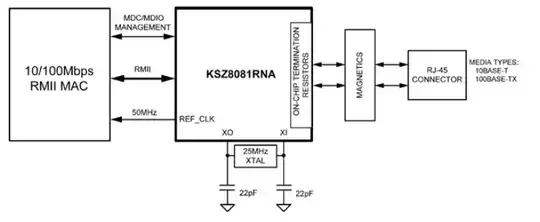
The DART-6UL/DART-6UL-5G features Micrel™ KSZ8081RNL Ethernet PHY. KSZ8081 is a single supply 10Base-T/100BaseTX Ethernet physical-layer transceiver for transmission and reception of data over standard CAT-5 unshielded twisted pair (UTP) cable.

Here is the datasheet for the KSZ8081RNL

enter image description here

Typically you place magnetics between the phy and the outside world (as per the spec), if the phy's are on the same board, you may not want to use magnetics. Read the datasheet of the KSZ8081 and follow the guidelines. I'd estimate someone who has not implemented an ethernet interface would need about 30 to 60 hours to read and understand all of the material required to correctly implement the interface. Lucky for you the phy is already on the board so using that should save you some time. You need to make sure the routing is done using impedance controlled (usually 100Ω check the datasheet) traces.

Voltage Spike
  • 75,799
  • 36
  • 80
  • 208
0

Ethernet PHY (physical layer) on your board is implemented with Microchip's KSZ8081 controller. Check Fig. 7-16 at page 58 of the datasheet: enter image description here Pins TXP, TXM, RXP and RXM corresponds to pins ETH_RXDP, ETH_RXDN, ETH_TXDP and ETH_TXDN at J1 connector of your board (page 19 of the datasheet you provided). I suggest you to use RJ45 connector with integrated transformer and common mode choke, as this one.

Besides RJ45 connector you need only two additional capacitors, so routing is fairly simple. Keep tracks as short as possible and the same length.

Davor
  • 43
  • 1
  • 4
  • So to be clear : there will be the RJ45 connector, connected to a magnetic, which will directly be connected to the Ethernet ports on the nano-computer. Am I right ? Is there a need for a transformer ? Or are the magnetic/transformer the same thing ? Sorry I'm a bit confused but with your explanations and the reading of the datasheet it becomes clearer :) – JackOfHearts Jan 03 '19 at 11:37
  • Magnetics = Transformer – Tom L. Jan 03 '19 at 11:44
  • Yes. I suggest you to use RJ45 connector with transformer, like [this one](https://export.farnell.com/wurth-elektronik/74980111211/conn-rj45-w-lan-transfrmr-8p8c/dp/2407403). Then you can directly apply schematic from the datasheet. – Davor Jan 03 '19 at 13:20