First time poster here, please excuse holes in the plot.
I have a simple wireless design made of an MCU (atmega328p) and an NRF24L01 module, powered through a 3.3V regulator, talking to a similar board on the other side. This has been working well so far as a through-hole design, so I made a surface-mount version.


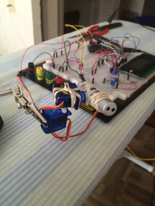
Through-hole version above, SMD version below.
As you can tell, the RF module sits above some of the components of the board, although I took care to not put any copper under the antenna. In the through-hole version, there is no copper or components at all under the whole module. There are also a few other differences that I believe don't matter here (the SMD version does not using any crystal, adds some fuses, uses different I/O pins).
With the through-hole version, I could easily get over 10m range. With the SMD version, most messages do not get received even when the boards are cm apart (the receiving end is the same in all tests, in this case an Arduino Nano hooked to a similar RF module).
What I have noticed, though, is:
- When I power the board via the ICSP port (bypassing the regulator), transmission works fine (I thought this might indicate not enough capacitance, but adding a 470uF cap in parallel doesn't fix anything, so I don't thing it's that)
- When powered through the regulator (target use case), transmission fails unless I do one of these:
- Putting my finger on the VCC or MISO pin of the ICSP port (putting my finger on any other ICSP pin doesn't change anything. Touching the same VCC and MISO signals anywhere else on the board doesn't make transmission work).
- Touching the antenna with a finger or a few cm of wire
- Reducing PA level to MIN or LOW (but that reduces range to just a couple meters). I originally had it set to MAX or HIGH.
My impression is that my design is somehow screwing up the RF module's antenna, and touching some specific parts of the board with a wire or a hand somehow corrects for that and allows the signal to be sent correctly. But as I know close to nothing of RF transmission, I don't know exactly what I am doing wrong.
I am happy to change my design, but I would like to understand what is wrong with it and in which direction I must take it.
Is it being disturbed by the chips under the module, or does this not matter? Is the clearance I gave the antenna not wide enough, or on the contrary, should I have not put any clearance under the antenna in the first place? Should I just solder some extra wire to the antenna (if so, how much? and why?)
I just don't really know which way to go and I'd rather avoid building 100 versions to find out. I'm also not sure of what I can do to find out more (right now the most sophisticated tool I have at my disposal is a multimeter - could a scope tell me more?).
Edit, answering the comments:
- Yes, connecting the RF module through jumper wires also makes transmission work.
- I cannot find any evidence of the RF module getting its power through the IO pins instead of the power rail. I am seeing 3.3V all the way through to the module.
- The regulator is pretty much the same. They're both 1117V33 types. The SOT23 is a AZ1117IH, the TO220 is a LD1117V33.