3

Our (old) boat has a fresh water tank whose level was reported by a now broken gauge. For cosmetic reasons I need to replace the broken gauge with a similar form factor (I do not wish to cut the panel about). So I cannot just buy any new tank gauge.

The old gauge is from the Anders Acclaim AM25 series and had been adapted (messily) to act as an Ommeter with a "Euro type" tank sender. I can obtain a physically compatible replacement ammeter (1 milliamp max) and I can change the tank sender to the "US type" (240 ohms empty, 33.5 ohms full).

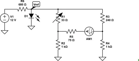
But I cannot work out what circuit to build such that the gauge will read zero amps when the tank is empty and 1milliamp when the tank is full.

Boat's electrics are a nominal 12v (more like 12.5 when exhausted and 14.4 when charging).

Edit: the replacement ammeter is described as having a coil resistance of 200ohms here http://www.topqualitytools.co.uk/meter-78x60-0-1ma-am25a2/

Edit: Further hunting has produced an alternative compatible gauge, a voltmeter, the AM25F2 (0-75mV DC). Might this be utilised in a solution?

  • Can you measure the resistance of the meter and add it into your question? It will affect the solution. The [AM25MA1 datasheet](http://www.farnell.com/datasheets/53014.pdf) doesn't list it. – Transistor Dec 25 '18 at 12:08
  • Two nice answers, which one will you accept? – Solar Mike Dec 25 '18 at 18:32
  • Since I am prompted, I will happily accept @Transistor's answer, but am unsure if if I yet should given the updates to my original question? – Lance Kneeshaw Dec 25 '18 at 20:50
  • 1
    Wait until the Earth rotates once or twice to give the whole of humanity a chance to answer. You might get some other ideas if you don't dissuade contributors by accepting too quickly. Thanks. – Transistor Dec 25 '18 at 20:55
  • As elsewhere noted - use a TL431 for the "zener" reference. This is a "variable zener" which is available in 2% 1% and 0.5% (AFAIR) versions. Usually costs 10's of cents and is FAR better than a zener in too many ways to name here. Ask if more info wanted. – Russell McMahon Dec 26 '18 at 02:34

2 Answers2

5

schematic

simulate this circuit – Schematic created using CircuitLab

Figure 1. An imbalanced bridge solution. R5 is the assumed resistance of your milliammeter.

I offer this as a rough and ready solution to your question. It is based on the principle of the Wheatstone Bridge which, when the ratios of R1:R2 = R3:R4 are matched will have zero current through R5 and AM1. R3 is set at 240 Ω so that balance occurs when the tank is empty and the meter will read zero.

The values for R2 and R4 were established by messing around with the CircuitLab simulator (which you can do by editing my question - just don't save it) rather than going through all the maths.

To keep the values of R2 and R4 reasonably low and avoid you having to do precise resistor matching we need to drop the bridge voltage down to about 2 V or so. R6 and D1 do this. The forward voltage, Vf, of an LED is reasonably constant over a range of currents so this voltage will remain reasonably constant with variation in battery voltage. The 680 Ω resistor will give about 15 mA. A red, yellow or green LED will give around 2 V at this current. Blue and white would give a higher voltage.

enter image description here

Figure 2. LED I-V curves for various colours of LED. Green will give a 2 V drop at around 15 mA. Source: LEDnique.


Update:

For a 1 mA, 200 Ω meter R2 and R4 should be reduced to about 680 Ω.

Transistor
  • 168,990
  • 12
  • 186
  • 385
  • Hrm, perhaps a TL431 would make a good shunt ref for this application? Going to be a bit more accurate than the LED-reference-bodge, and still pretty cheap/easy to obtain? – ThreePhaseEel Dec 25 '18 at 18:42
  • I chose components that the OP might have to hand on Christmas Day. – Transistor Dec 25 '18 at 19:26
  • Well, a dead switching supply is likely to have a TL431 in it (albeit in SOT23 :P), but that is a point, depends on how well stocked your junkbox is ;) – ThreePhaseEel Dec 25 '18 at 19:28
  • Frankly I am astonished at the elegance of this, and grateful for the investment of time it took in designing. I particularly appreciate the "might have to hand" consideration. – Lance Kneeshaw Dec 25 '18 at 20:44
  • I've just updated for the 200 ohm measurement you took. As I said, it's rough and ready but could be more than sufficient for your application. – Transistor Dec 25 '18 at 20:46
3

@Transistor (+1) has a pretty similar circuit posted before I finished this (Xmas breakfast and all) but I'll include this as an option.

The 500 ohm pot trims the "full" level. If you want to trim the empty (which is arguably more important, replace the 240 ohm resistor with something like 200 ohms in series with a 100 ohm trimpot.

schematic

simulate this circuit – Schematic created using CircuitLab

BobT
  • 1,714
  • 13
  • 12
Spehro Pefhany
  • 376,485
  • 21
  • 320
  • 842