13

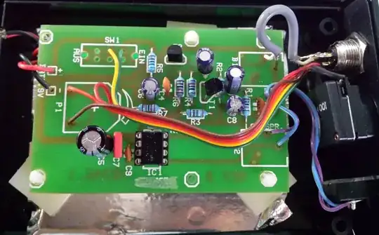
Currently, this is the only assembled part on the circuit board. This is a simple inverting buffer circuit that should be at the input. The op-amp (LTC6241HV) is powered +/-5V from a linear bench power supply. The power pins are bypassed with 0.1uF caps.

I'm inputting a 1KHz sine and on the output I get a ~405KHz sine superimposed on the 1KHz signal. I have tried to build a second PCB but the results are exactly the same.

If anyone knows what could be the cause for this I'll be happy to hear.

LTC6241HV Datasheet enter image description here

user733606
  • 435
  • 4
  • 14
  • 6
    Wow, 1MEGohm: that's dangerous. Try reducing R1, R3. – glen_geek Dec 22 '18 at 14:41
  • @glen_geek to something like 470K? I still need a high input Z. – user733606 Dec 22 '18 at 14:42
  • 3
    Most problematic: The capacitor C6 which gives the loop gain a lowpass characteristic. As a result, additional phase shift which reduces the phase margin - in particular because of unity gain configuration – LvW Dec 22 '18 at 14:44
  • 3
    If you need high-Z, then add a tiny capacitor (even a few pf) across R1 in parallel. That should help kill oscillation. But be aware that the high-frequency response is affected. An optimum value should allow flat response to about 1 MHz. – glen_geek Dec 22 '18 at 14:47
  • 2
    If you cannot reduce R3 (at least to 100k, better if even lower) you can shunt R1 with a capacitor, setting say 100kHz or lower bandwidth. Otherwise, you can shunt non inverting input to ground with, say 100kohm or so, reducing loop gain. – carloc Dec 22 '18 at 14:52
  • @glen_geek I'll try that. The highest freq. this circuit would normally see are below 1MHz. – user733606 Dec 22 '18 at 14:53
  • 10pf and 500K Ohm is 0.5uS tau, or 300KHz F3dB (and 45 degree phase shift). Given the phase margin, this is about where the circuit should oscillate. – analogsystemsrf Dec 22 '18 at 17:28
  • 3
    Has anyone asked about the load capacitance for this problem? With any cable you will xx pF/m and the datasheet specifies the series R vs load pF for stability reasons. Why did you choose this device for -1 gain? What is the load pF? – Tony Stewart EE75 Dec 23 '18 at 03:00

2 Answers2

21

Chip suppliers are keen that their users avoid common design errors, shown by application examples in their data sheets. This one is addressed by Linear Technology in their data sheet for LTC6241. It also applies to many other opamps:

The good noise performance of these op amps can be attributed to large input devices in the differential pair. Above several hundred kilohertz, the input capacitance rises and can cause amplifier stability problems if left unchecked. When the feedback around the op amp is resistive (RF), a pole will be created with RF, the source resistance, source capacitance (RS, CS), and the amplifier input capacitance. In low gain configurations and with RF and RS in even the kilohm range (Figure 4), this pole can create excess phase shift and possibly oscillation. A small capacitor CF in parallel with RF eliminates this problem.

schematic

simulate this circuit – Schematic created using CircuitLab

glen_geek
  • 23,591
  • 1
  • 22
  • 50
  • 1
    +1 One of the CMOS-input parts I've used a lot has a front end that consists of scores of MOSFETs in parallel, arranged in an X-Y array with half the transistors for each input. That way the variations across the wafer are minimized and Vos is minimized. Neither that nor the consequences (high input capacitance) are disclosed in the datasheet despite being aimed at low power applications where high value feedback resistors are common. So maybe TI isn't as keen as LTC was. – Spehro Pefhany Dec 22 '18 at 20:26
  • 1
    As was suggested by **glen_geek**, I've added a 15pF cap across R1. At the freq. of oscillation (~400KHz) this has an effective impedance of just over 25KOhm. Paralleled with 1MOhm R1 this figure remains almost unchanged. At that freq. the gain is about -0.025 so high freq. get filtered out. The output is now an inverted sine wave, as was expected. Thank you all for your contributions! – user733606 Dec 22 '18 at 15:15
  • *At that freq. the gain is about 0.025 so high freq. get filtered out.* Can you explain what you mean by that? I thought the gain of this op-amp is (-1). How did it get to 0.025 and why is it affected by the frequency? – nettek Dec 22 '18 at 15:36
  • @Eran at 400Khz the 15pF cap has an impedance of about 26.5Kohm and R1 almost does not change that figure so the gain that the op-amp has at that freq. is -26.5K / 1M = -0.0265 which is attenuation at that higher freq.. This is compared with the gain at a lower freq. of say 5KHz where the cap has much higher impedance so the gain of the opamp is closer to -1. This is a typical behavior of a low pass filter. – user733606 Dec 22 '18 at 15:49
  • Right! Even though you wrote that, I didn't think about the impedance of the capacitor and resistor in parallel changing the overall gain of the op-amp - I thought the gain was still (-1) because there are two 1M resistors. Thanks! – nettek Dec 22 '18 at 16:05
  • Are you aware that you've reduced the usable bandwidth to approx 10kHz, is this okay with your audio application? – carloc Dec 22 '18 at 17:20
  • @carloc that's true. I better make it 2.5pF – user733606 Dec 22 '18 at 18:08
  • @user733606 - Good idea. Maybe. Be aware that there is a certain minimum feedback capacitance required to avoid instability, and that may be more than 2.5 pF. Even if the circuit doesn't (quite) oscillate, make sure you look at the output with a step input. You may see an underdamped response, with an initial overshoot followed by a diminishing oscillation (called "ringing"). If so, you'll need to increase the capacitance a bit. – WhatRoughBeast Dec 23 '18 at 16:31
1

To balance the circuit, you need a 499K resistor in series with the (+), pin 3, input. It will cancel any offset and possibly solve your oscillation problem.

Dan_LXI
  • 56
  • 3