I want to say that I am not a native English speaker so you may find some writing errors. Also, I am just learning electronics, so sorry if some questions are poorly formulated.
I am trying to build a proximity alarm. In order to achieve this, I want to compare an electrical signal from a distance measuring sensor unit (you can find its datasheet here: Datasheet). This sensor gives me a signal from 20 to 150 cm, so, what I want to occur is for the alarm to turn on when something is blocking the sensor at approximately 40 cm.
To generate this comparator, I am using a Schmitt Trigger. I set up (experimentally) the resistances in order to give a threshold of 40 cm. Here is the schematic.
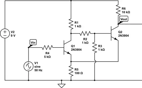
simulate this circuit – Schematic created using CircuitLab
I have found the desired output, but with some problems:
- The actual thresholds are not equal to the theoretical thresholds.
- When I connect a buzzer in parallel with the output, the voltage falls a lot and it sounds very low. How can i fix this?
And the questions are:
- Why are the experimental and theoretical thresholds not equal?
- How can I couple a simple buzzer?
- Is the biasing correct?
- If I want to add an LED, how can I connect it?
PD1: The input wave is there just to give a reference because I can't simulate the sensor.
PD2: The calculations of the thresholds:
\$V_{high} = \frac{R3}{R1+R2+R3}V_{CC} - 0.7\text{ V} = 2.3\text{ V}\$
\$V_{low} = \frac{R3}{R1 + R2 + R3 + \frac{R1 \cdot R3}{R5}}V_{CC} + 0.7\text{ V} = 2.78\text{ V}\$